Sla je deck op voordat het weg is
Deze flashcards zijn nog niet opgeslagen — ze verdwijnen zodra je weggaat. Maak een gratis account aan om ze te bewaren en krijg toegang tot alles hieronder.
- Save this deck to your account
- Study with spaced repetition
- Export to Anki (.apkg) or PDF
- Process documents up to 100 pages
- Images extracted from your PDFs
- Sharper text extraction & a more advanced AI model
Objective 1 covers describing the shift based operator responsibilities for
water treatment plants
process areas
turbine houses
boiler plants
Operators must perform many checks while
during maintenance
before handover
on shift
off shift
Prior to the start of a shift, it is essential to have a handover discussion with the
previous shift members
plant manager
assistant shift engineer
maintenance crew
After the log book is read, log sheets are reviewed, and the shift handover is complete, the Power Engineer coming on shift must immediately become familiar with the
frequency of checks
operating condition of the plant
manufacturer operations manuals
site-specific procedures
Commonly, the Power Engineer becoming familiar with the operating condition of the plant is referred to as doing
tests
log sheet entries
rounds
handover
Always consult manufacturer operations manuals and site-specific procedures to determine what should be checked, and the
number of shifts
duration of rounds
frequency of checks
number of engineers
Rounds often include tests and
handover discussions
manufacturer manual reviews
formal log sheet entries
process area inspections
A comprehensive set of rounds may take
one full shift
thirty minutes
one to two hours
three to four hours
The person who usually performs the boiler plant rounds is
the junior boiler operator
the shift engineer
the plant owner
the night watchman
The proper set point for boiler water level is
at the bottom of the gauge glass
filling the entire gauge glass
about half way up the gauge glass
at the very top of the gauge glass
The condition for boiler pressure is that it should be
varied randomly regardless of steam demand
at or above the high-pressure cut-off setting
at or near set point, near the same pressure as the steam header, and below the setting of the high-pressure cut-off
completely independent of steam header pressure
The maintenance check for boiler feed pumps includes
only unusual noise and vibration
only discharge pressure and leaks
only lube oil temperature
vibration, unusual noise, leaks, and discharge pressure
Rusty coloured condensate is an indicator of
excessive lube oil
normal water hardness
corrosion in the condensate return system
high condensate pH
The maintenance check for pumps that transfer condensate from the receiver to the deaerator includes
vibration, unusual noise, leaks, and discharge pressure
only discharge pressure and leaks
only unusual noise and vibration
only lube oil pressure
Water flowing from the condensate tank vent is an indication that
the condensate return system is normal
the condensate return pump has failed
the steam traps are working correctly
the condensate tank is full
Deaerators typically operate between
70 and 200 kPa
70 and 400 kPa
50 and 300 kPa
100 and 500 kPa
Deaerator vent valves should be kept
partially open
open
throttled
closed
If the water temperature is below the saturation pressure of the steam, the deaerator vent is likely
obstructed
venting
normal
closed
For a deaerator operating at 99 kPag, the approximate absolute pressure is
200 kPa
99 kPa
299 kPa
150 kPa
For a deaerator operating at 299 kPag, the expected deaerated water temperature is 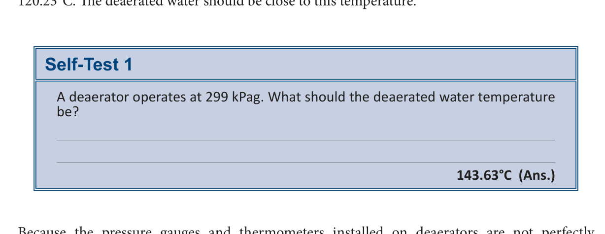
105°C
143.63°C
120.23°C
115°C
Pressure gauges and thermometers installed on deaerators are
calibrated periodically
not perfectly calibrated
highly accurate
always precise
Equipment checks for pumps include looking for
vent valve position and steam pressure
water levels, brine levels, and salt amounts
flow totalizers and regeneration cycles
vibration, noise, discharge pressure, and leaks
Sodium zeolite softeners require the presence of
clear water tanks
brine level indicators
flow totalizers
un-dissolved lumps of salt
Ion-exchange softeners are equipped with
vent valves
flow totalizers
pressure gauges
thermometers
Boiler temperature relative to set point and high temperature cut-off is
at set point and exactly at high temperature cut-off
at or near set point, and below the high temperature cut-off set point
above set point and above high temperature cut-off
below set point and above high temperature cut-off
Water level in the expansion tank gauge glass should be
at the very top
about half way
entirely empty
at the very bottom
Action required if shaft leakage of hot water circulating pumps is excessive is to
increase discharge pressure
adjust the pump packing
clean the intake screen
replace the bearings
Fireside obstruction causing excessive draft loss in furnace draft gauges may result from
excessive dilution air
excessive pump packing
boiler leaks or soot accumulations
damaged drive belts
Factors causing abnormally high flue gas temperatures include over-firing, too much excess air, or
heat exchanger fouling
damaged intake louvres
symmetrical flame shape
excessive flame soot
Desirable flame characteristics include being bright, free of soot, and
vigorous and symmetrical in shape
low in temperature and asymmetrical
impinging on heat transfer surface
puffing during ignition
Intake screen and louvre corrosion checking is especially important in coastal areas due to
excessive frost and snow
build-up of debris
salt spray carried by the wind
high combustion air pressure
The person usually conducting the plant rounds is the
maintenance technician
assistant shift engineer
plant manager
chief engineer
The component identified as the heart of the power plant is the
boiler
standby generator
air compressor
air receiver
Water is removed by blowing off the base of the
air receiver
aftercooler
coalescing filter
moisture trap
The compressor pressure to confirm operating according to manufacturer's specifications is the
lube oil pump pressure
inlet air pressure
receiver pressure
coolant pressure
Modern air dryers use sensing devices to determine
dew point
receiver pressure
filter differential
inlet temperature
Refrigerated air dryers require blowing off liquids from the moisture trap and the
air receiver
coalescing filter
inlet air filter
aftercooler
Electric start diesel and gas engines require checking the battery charger and the
lube oil pressure
electrolyte levels
distilled water pressure
air receiver pressure
Compressed-air start diesels require ensuring the dedicated air receiver has the correct
compressed air pressure
water level
oil pressure
electrolyte level
Engine block heater operation ensures the engine is
lukewarm to touch
freezing to touch
cold to touch
warm or hot to touch
Lube oil pressure and temperature checking ensures they meet
cooling requirements
engine capacity
manufacturer specifications
operational standards
Diesel engines rely on day tanks to provide
hydraulic fluid
lubricating oil
cooling water
fuel oil
Generator automatic transfer switch settings require
manual
standby
automatic
off
Spilled materials require
proper disposal
chemical neutralization
immediate recycling
burial
Chemicals that are incorrectly stored or lack proper WHMIS labelling require
immediate incineration
returning these materials to proper locations
dilution with water
placement in general trash
Tools, hoses, brooms, extension cords, or temporary equipment potentially represent
tripping hazards
chemical risks
structural hazards
electrical fires
Plant areas with burned out luminaires require
reporting to security
immediate shut down
reporting to the shift engineer
replacement by maintenance staff
Engineers during ongoing power plant maintenance must be aware of tripping hazards created by
drain hoses or power cords
water columns
isolation valves
steam connections
A water column blowdown should be completed at the beginning of
every maintenance cycle
every week
every hour
every shift
Upon taking charge of a boiler, the first check should be for
adequate water level
adequate steam pressure
valve position
blowdown completion
The operator must ensure that the water column is not
pressurized
leaking
isolated
obstructed
High-pressure steam boiler isolation valves between the water column and the boiler must be locked in the
closed position
open position
bypass position
neutral position
The initial action required before checking water column connections is to
Open the water column drain valve
Close the water column water valve
Remove the locks or seals from the water column isolation valves
Close the gauge steam and water valves
Closing the water column water valve and opening the water column drain valve allows
Steam to blow through the steam connection and the water column
Steam to blow through the water connection
Water to flow through the steam connection
Water to flow through the water column
Closing the water column steam valve and opening the water column water valve provides proof that
The gauge glass connection is clear
The drain valve connection is clear
The water connection passage is clear
The steam connection passage is clear
Opening the gauge glass steam valve followed by the gauge glass drain valve allows
Water to flow through the top gauge glass connection
Steam to blow through the bottom gauge glass connection
Steam to blow through the top gauge glass connection
Water to flow through the bottom gauge glass connection
Closing the gauge glass steam valve and opening the gauge glass water valve proves
The lower gauge glass connection is clear
The upper gauge glass connection is clear
The gauge glass drain valve is clear
The water column steam connection is clear
Closing the drain valve and opening the gauge glass steam valve results in
Steam filling the gauge glass entirely
The water level dropping to the bottom
The water rising quickly to its true level
The isolation valves closing automatically
Most high-pressure steam boilers and all low-pressure steam boilers do not have
Gauge glass drain valves
Water column drain valves
Isolation valves in the steam and water piping between the water column and the boiler
Gauge glass steam valves
Closing the gauge glass water valve (B) prevents
sediment from collecting in the gauge glass
pressure from reaching the gauge glass
steam from flowing through the gauge glass
water from flowing through the gauge glass
Opening the water column drain (C) allows
steam and water to enter the gauge glass
steam and water to circulate through the gauge glass
steam and water to blow through the connections to the drain
steam and water to empty from the boiler drum
Closing the water column drain valve (C) and opening the drain on the gauge glass (D) serves to
replace the gauge glass washer
clean the sediment from the gauge glass
prove the steam connection and the gauge glass are clear
prevent the check ball from seating
Closing the gauge glass steam valve (A) and opening the gauge glass water valve (B) serves to
prove the steam connection is clear
shorten the life of the mica
prove the water passages on the gauge glass are clear
remove sediment from the gauge glass
Closing the gauge glass drain valve (D) and opening the gauge steam valve (A) is the procedure used to
shorten the life of the mica
clean the gauge glass connection
remove internal corrosion
put the gauge glass back in service
The water column and gauge glass should be blown down every shift to
shorten the life of the mica
prevent the check ball from seating
renew internal corrosion
remove any sediment that may collect
Gauge glasses should be renewed if they become obscured by
ball check seating
internal corrosion or deposits
sediment or mica
external damage or moisture
If gauge glass isolation valves are of the safety ball check type, the valves must be partially closed to
prevent the check ball from seating
remove any sediment that may collect
prove the steam connection is clear
shorten the life of the mica
Safety shut-off gauge glass valve component positioned between the check ball and the valve stem seat is the
Check ball seat
Gauge glass connection
Boiler or water column connection
Valve stem
Feedwater control valve position is often indicated on the
Valve stem seat
Check ball seat
Check ball
Valve stem
Testing the operation of the feedwater control valve begins by closing the isolation valve
On the boiler connection
Upstream of the feedwater valve
In the gauge glass
Downstream of the feedwater valve
Control valve component providing visual information on the valve position is the
Gauge glass drain connection
Check ball seat
Valve stem
Valve position indicator
Steam traps that are plugged cause
condensate to flood heat exchangers and impede heat transfer
a complete stop in steam distribution
excessive pressure buildup in the return tank
a decrease in energy efficiency throughout the plant
increased condensate flow through the bypass
Constant steam issuing from condensate return tank vents is one indication of
a malfunctioning bypass valve
excessive pressure in the condensate return
a leaking isolation valve
a failed steam trap
a clogged sediment strainer
A direct method of checking a steam trap involves closing the isolation valve downstream of the trap and opening 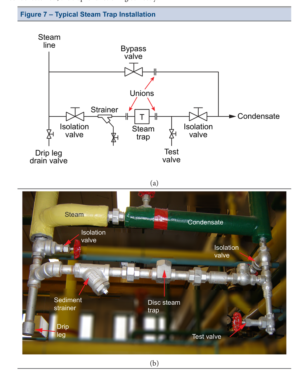
a test valve located downstream of the trap
the main steam line valve
the drip leg drain valve
the bypass valve
the upstream isolation valve
A constant flow of steam from the test valve is a sure indication that
the condensate line is blocked
the bypass valve is open
the strainer is clogged
the trap is functioning correctly
the trap has failed
If there is intermittent condensate flow from the test valve, the trap is
failing
isolated
flooded
functioning correctly
plugged
Most steam traps are not installed with
infrared thermometers
test valves
indirect methods
temperature differences
Traps can be checked using
visual inspection
direct methods
indirect methods
test valves
A hand-held infrared thermometer is used to compare the
trap pressure to the atmospheric pressure
trap inlet temperature to the ambient temperature
trap inlet temperature to the trap outlet temperature
trap volume to the capacity
No temperature difference indicates
the steam trap is leaking
the steam trap is overheating
the steam trap is operating correctly
the steam trap has failed
Performing regularly scheduled checks on safety devices ensures
a low-pressure boiler system
a manual-fired boiler plant
a high-limit controlled boiler plant
a safe and reliable boiler plant
ASME CSD-1 Controls and Safety Devices for Automatically Fired Boilers recommends a weekly check of the
high limit controls
boiler flame failure detection systems
low water cut-offs
combustion control systems
Operating manual supplied by the boiler manufacturer regarding the proper procedures for testing and maintenance of safety limit controls must be
replaced
ignored
updated
consulted
ASME BPVC VI describes the recommended procedure for testing
low water cut-offs
combustion controls
flame safeguard devices
main burner valves
For a Gas Burner with a Thermocouple or Thermopile Flame Sensor, testing the device requires the operator to close the main burner test firing valve with the
main burner turned off
main burner firing normally
safety shut-off valve closed
pilot burner turned off
For a Gas Burner with an Electronic Flame Rod and Continuous Pilot, closing the pilot burner test firing valve should result in the safety shut-off valve closing in
four seconds or less
two seconds or less
six seconds or less
ten seconds or less
Gas Burner with Electronic Flame Rod and Interrupted Pilot main burner test firing valve closing time for the safety shut-off valve to close is
two seconds or less
ten seconds or less
four seconds or less
six seconds or less
Gas Burner with Electronic Flame Scanner safety shut-off valve closing time after removing the scanner from its sighting tube and covering it is
four seconds or less
six seconds or less
two seconds or less
ten seconds or less
Oil Burner with Electronic Flame Scanner oil solenoid valve closing time after closing the manual test firing valve in the oil supply line is
ten seconds or less
four seconds or less
six seconds or less
two seconds or less
Checking Pilot Flame Failure Response condition when the pilot burner test firing valve is closed is that the main burner test firing valve must also be
reset
opened
energized
closed
Checking the main flame failure response prior to checking the pilot flame failure response is
Not to be done
A recommended test
Required for consistent ignition
A standard safety procedure
The combustion control lockout switch should be reset after closing
The light-sensitive element
The main fuel safety shut-off valve
The main burner and pilot burner test firing valves
The pilot flame scanner
Following the pre-purge period, the main burner will not ignite because
The scanner fails to sense the flame
The fuel safety shut-off valve fails to energize
The main burner test firing valve is closed
The pilot flame is unstable
After the main flame trial for ignition period is over, the main safety shut-off valve will
De-energize
Recycle
Remain open
Energize
The only maintenance required for the programmed combustion control is
Replacement of the flame rod daily
Cleaning of flame amplifier tubes
Annual replacement of the drum control sequencer
Occasional blowing out of accumulated dust
Cleaning of slightly oxidized or dirty contact points is performed by
Filing the contact points
Replacing the electronic tubes
Applying a solvent to the contacts
Drawing a piece of hard finished paper between the contacts
The scanner tube requires an adequate air supply to
Keep it cool
Increase life span
Improve flame discrimination
Prevent carbon buildup
Ultraviolet flame scanners have a service life of approximately
20,000 hours
10,000 hours
80,000 hours
40,000 hours
Recommendations for annual replacement of flame rods and scanners are provided by
ASME CSD-1
The programmed combustion control manufacturer
The drum control sequencer manual
The light-sensitive element specifications
ASME CSD-1 recommends the frequency for testing the low gas pressure cut-off switch be
yearly
weekly
monthly
quarterly
ASME CSD-1 recommends the frequency for testing the high gas pressure cut-off switch be
annually
daily
biannually
monthly
ASME CSD-1 recommends the frequency for testing the combustion air proving switch be
every six months
hourly
monthly
every two years
The try lever test (or manual check) determines the
relieving capacity
popping pressure
blowdown
freedom of valve movement
The pop test (or pressure test) determines the
relieving capacity
popping pressure and blowdown
freedom of valve movement
air pressure
The accumulation test determines the
popping pressure
blowdown
relieving capacity
freedom of valve movement
Safety valve check frequencies are outlined in the ASME BPVC VI and VII and the
Manual try lever
Boiler log book
ASME BPVC I
NBBI Inspection Code
Try Lever Test frequency for a Hot Water Heating Boiler is
Semi-Annual (NBBI)
Quarterly (NBBI)
Monthly (ASME BPVC VI)
Annual
Manual try lever tests require the boiler to be in service and
in the heating season
under pressure
at full capacity
in the boiler log book
Heating boilers in steam service require a minimum pressure of
5 to 10 seconds
35 kPa
75 kPa
2760 kPa
Heating boilers in steam service with valves that continue to simmer after the test require
manual try lever reset
log book documentation
immediate shutdown
replacement or repair
Power boiler safety valves should not be opened with hand lifting gear when the steam pressure is less than
2760 kPa
75% of the set pressure
50% of the set pressure
35 kPa
The pop test should be performed when taking a boiler off-line for
daily startup
annual maintenance
routine inspection
emergency repairs
Prior to performing a pop test, the boiler steam outlet and feedwater supply valves should be
opened
closed
bypassed
purged
On an automatically fired boiler, the operating control and the high limit control must be
de-energized
replaced
calibrated
bypassed
If the safety valve fails to open at the required pressure, the operator should
hammer the valve body
shut off the burner
bypass the high limit control
increase the steam pressure
The caution regarding a stuck safety valve specifically prohibits
hammering or striking the valve body
releasing the steam pressure
performing a try lever test
removing the valve from service
ASME BPVC IV, Part HG-400.1 states that steam boilers shall have safety valves adjusted and sealed to discharge at a pressure not to exceed
17 psi
15 psi
13 psi
2 psi
ASME BPVC VI, Part HG-400.1 states that set pressure tolerances shall not exceed
13 psi
17 psi
2 psi
15 psi
Safety valves controlled blowdown requirement as stated by ASME BPVC IV, Part HG-401.1(e)
4 psi to 6 psi (30 to 40 kPa)
1 psi to 2 psi (7 to 15 kPa)
3 psi to 5 psi (20 to 35 kPa)
2 psi to 4 psi (15 to 30 kPa)
Blowdown calculation determined by subtracting the closing pressure from the opening pressure for a low-pressure steam boiler safety valve that pops open at 95 kPa and has an acceptable reseat pressure range of
75 to 90 kPa
85 to 95 kPa
55 to 70 kPa
65 to 80 kPa
Table 2 set pressure tolerance for steam power boilers with a set pressure greater than 500 kPa and less than or equal to 2100 kPa
1% of set pressure
15 kPa
70 kPa
3% of set pressure
Pressure relief valves designed and constructed to operate without chattering with a minimum blowdown as stated by ASME BPVC I, Part PG-72.1
3 psi (20 kPa) or 3% of the set pressure, whichever is greater
2 psi (15 kPa) or 4% of the set pressure, whichever is greater
4 psi (30 kPa) or 2% of the set pressure, whichever is greater
2 psi (15 kPa) or 2% of the set pressure, whichever is greater
A high-pressure steam boiler safety valve set to open at 1035 kPa has an acceptable range of popping pressures of
1015 to 1055 kPa
1000 to 1035 kPa
1004 to 1066 kPa
1035 to 1100 kPa
The minimum acceptable blowdown for a high-pressure steam boiler safety valve set to open at 1035 kPa is
21 kPa
31 kPa
42 kPa
10 kPa
Safety valves that do not respond within the code-mandated popping and reseating parameters must be
either replaced or refurbished by a certified valve repair agency
removed from service permanently
tightened by adjusting the spring tension
recalibrated immediately by the operator
An accumulation test is performed when the
safety or safety relief valve capacity cannot be determined
main steam outlet is fully open
boiler requires a routine start-up
feedwater system is shut down
During the preparation for an accumulation test, the pressure limit controls are
bypassed with jumpers
manually operated by the technician
set to maximum load
isolated from the steam drum
The ASME BPVC I Part PG-67.2 states that the pressure relief valve capacity for each boiler shall be such that the pressure relief valve or valves will discharge all the steam that can be generated by the boiler without allowing the pressure to rise more than
10% above the highest-pressure at which any valve is set
6% above the highest-pressure at which any valve is set
15% above the highest-pressure at which any valve is set
3% above the highest-pressure at which any valve is set
Maximum acceptable pressure during an accumulation test for a boiler with a MAWP of 1380 kPa and a safety valve set to 1310 kPa is
1380 kPa
1310 kPa
1389 kPa
1400 kPa
Maximum pressure during an accumulation test for a high-pressure steam boiler with a MAWP of 1725 kPa and a safety valve set to 1725 kPa is 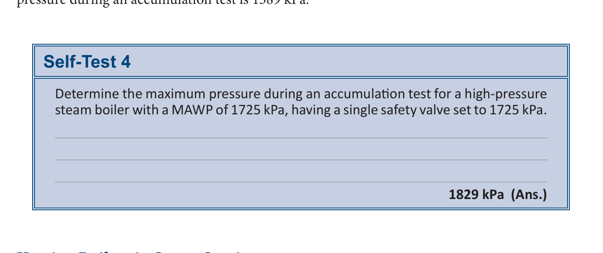
1829 kPa
1850 kPa
1775 kPa
1725 kPa
Guidelines for conducting accumulation tests for heating boilers in steam service are located in
ASME CSD-1
ASME BPVC IV, Part HG-512
ASME BPVC IV, Part HG-400.1(e)
ASME BPVC IV, Part HG-400.2(f)
Pressure rise permitted for a heating boiler at maximum capacity above the maximum allowable working pressure according to ASME BPVC IV Part HG-400.1(e) is
3 psi (21 kPa)
6 psi (41 kPa)
5 psi (35 kPa)
10 psi (69 kPa)
Maximum pressure during an accumulation test for a low-pressure steam boiler with a MAWP of 100 kPa is 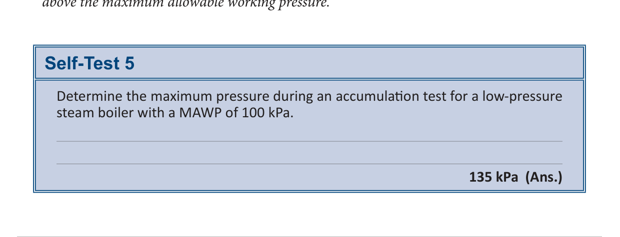
150 kPa
135 kPa
100 kPa
110 kPa
Automatic devices requiring regular attention to maintain proper operating condition are
Low water fuel cut-offs
Safety valves
Pressure controllers
Steam gauges
Frequency and types of tests recommended for low water cut-offs are outlined by
ASME BPVC IV, Part HG-512
ASME BPVC IV, Part HG-400.1(e)
ASME BPVC IV, Part HG-400.2(f)
ASME CSD-1
A rapid float chamber blowdown test involves
allowing the boiler to steam off water
removing the switch box cover
rapidly draining the float chamber
isolating the feedwater connection
ASME CSD-1 recommends that the float chamber blowdown test be completed for power boilers
annually
daily
semi-annually
weekly
The slow drain test involves isolating the feedwater and
draining the float chamber
blowing off the boiler
checking the switch box
steaming off water
ASME CSD-1 recommends that the slow drain test be completed
semi-annually
weekly
daily
annually
A test performed by isolating the feedwater and allowing the boiler to steam off water is recommended as
an alternative to the slow-drain test
a replacement for the float chamber blowdown
a mandatory procedure for power boilers
a daily requirement for all boilers
Steam boilers may use a combination boiler feedwater control and low water fuel
pump
valve
switch
cut-off
The make-up valve, which is connected directly to a float, can be checked by shutting down the feed
pump
boiler
valve
switch
Low water cut-offs, pump controls, and water feeders should be dismantled annually by qualified
personnel
operators
contractors
maintenance
Connecting lines to the boiler should be inspected for sediment and
corrosion
debris
scale
sludge
The operating limit switch does not require any special testing as its operation can be observed during routine boiler
inspection
repair
monitoring
operation
The high-pressure cut-off cannot be tested during normal boiler operation since it operates above the cut-off point of the operating
control
valve
switch
pump
The first step to test the high-pressure cut-off control is disconnect the
power
water
steam
valve
The high-pressure cut-off of a steam boiler should trip the boiler at a pressure higher than the set point of the operating limit control, but lower than the
operating limit pressure
safety valve popping pressure
burner operating pressure
steam pressure setting
Copper tubular and copper fin-tube boilers require positive water circulation to protect the heat transfer surfaces from failure due to
overheating
pressure loss
corrosion
low water level
When the circulating pump is operating, and the supply and return valves are open, the flow switch is
open
closed
satisfied
energized
In lieu of a low-water fuel cut-off device, automatically fired hot water boilers requiring forced circulation to prevent overheating shall be equipped with a
circulating pump
flow-sensing device
pressure gauge
safety valve
To test the flow switch, slowly close the boiler outlet valve and
drain the boiler
reset the control
check the pump
observe the burner
Hot water boilers and their piping systems are completely filled with water, and their low water cut-off float chambers are directly connected to the boiler above the
lowest permissible water level
highest operating pressure
return valve opening
safety valve setting
The ASME BPVC IV Part HG-614 states that a means shall be provided for testing the operation of the external low-water fuel cutoff without resorting to
shutting down the boiler
draining the entire system
operating the flow switch
removing the test lead
Special combination test and check valves restrict water flow to the float chamber when
the low water cut-off is tripped
the float chamber drain is opened
the boiler is drained
a sudden onrush of water occurs
ASME BPVC VI recommends testing the low water cut-off of hot water heating boilers
annually
daily
monthly
weekly
Operating limit switch operation is observed during
boiler startup
annual inspection
monthly testing
routine boiler monitoring
High temperature cut-off testing requires placing a test lead across the terminals of the
operating temperature control
firing equipment
boiler power supply
low water cut-off
ASME BPVC IV restricts the water temperature of hot water heating boilers to
110°C
100°C
115°C
120°C
Routine maintenance activities for boiler plant operation include blowing down drip legs, assessing packing leaks, and
repairing gauge glass leaks
lubricating feed pumps
cleaning furnace burners
replacing steam traps
Drip leg blowdown is commonly done
once a week
each shift
monthly
every hour
Drip leg blowdown removes excess accumulations of
steam particulates
condensate
boiler scale
valve lubricant
Gauge glass isolating valves occasionally leak through the
gauge glass stem
valve packing
drain connection
isolation seal
Gauge glass leaks often can be repaired while the boiler is
drained
shut down
depressurized
on-line
The valve packing will have to be tightened once the boiler is
on-line
depressurized
monitored
drained
The piping around the valve requires this specific action before tightening packing or valve bonnet gaskets
Heat
Flush
Depressurize
Lubricate
A leak located in the valve stem requires the tightening of the
Packing gland nuts
Steam pipe unions
Main valve handle
Bonnet flange bolts
The packing gland must be tightened in a manner that ensures it remains
Concentric to the bonnet
Perpendicular to the stem
Parallel to the flange
Horizontal to the pipe
Excessive compression of packing results in the valve becoming
Prone to rust
Impossible to open
Difficult to turn
Unable to seal
A leak occurring in the bonnet or flange necessitates the use of
A clockwise tightening sequence
A complete gasket replacement
A cross bolting pattern
A single point torque application
Stuffing boxes are designed to allow a continuous flow between the shaft and the
Bearing
Casing
Impeller
Packing
The leakage in a stuffing box task must not be completely stopped to prevent
Increased friction and motor overload
Packing overheating and pump shaft damage
Excessive vibration and bearing failure
Seal degradation and casing fatigue
SOPs not followed correctly result in
equipment damage or injury to personnel
excessive vibration
pump overheating
decreased pressure
The operator checks the box at the end of each step to
monitor discharge pressure
verify pump voltage
measure motor speed
keep track of where they are in the sequence
Startup procedure for a centrifugal pump step one is
Open suction valve
Close discharge valve
Confirm pump is primed
Open recirculation valve
Startup procedure for a centrifugal pump step six is
Select pump hand switch to ON
Close pump breaker
Close discharge valve
Confirm pump is primed
Procedures formatted with sign-offs that require the operator to place their initial at the end of each completed step identify
the cost of each activity
the pump type for each activity
the person who completed each activity
the duration of each activity
Centrifugal pump startup procedure requiring initials step one is
Close discharge valve
Open suction valve
Confirm pump is primed
Open recirculation valve
Practice of sign-offs is not
always used
the only tool
recommended
formally required
Tools for operators to help keep their place while following a procedure are needed because the practice of sign-offs is
not always used
rarely effective
often forgotten
too time consuming
Circle/Slash method requires that the operator must circle the step currently being
completed
noted
selected
conducted
Circle/Slash method requires that the operator put a slash through the circle when the step is
assigned
complete
reviewed
started
Highlight and Cross Out method requires that the operator highlights the step about to be
selected
performed
confirmed
started
Highlight and Cross Out method requires that the operator crosses out the entire step once
completed
started
selected
confirmed
The boiler room log functions as an official record of all activity and serves as a
boiler permit
training manual
maintenance schedule
legal document
A boiler log must provide a continuous record of boiler operation, including operating conditions, maintenance, and
purchase
warranty
installation
testing
Qualified personnel should test operating devices and protective equipment at sufficiently frequent intervals to determine that they are in
factory specifications
complete isolation
working condition
perfect alignment
Items commonly recorded in a log book include adjustment of controls, instructions for operators, safety valve testing, auxiliary equipment testing, and
fuel delivery
major maintenance jobs
staff scheduling
boiler cleaning
Completed boiler room log books must be available for review by the
Safety Coordinator
Boiler Inspector
Plant Manager
Equipment Manufacturer
Check and record items listed in the low-pressure heating boiler log consist of steam pressure, water level, feed pump pressure, feed water pressure, flue gas temperature, and
Burner operation
Oil pressure
Fuel supply
Alkalinity
Test items in the boiler log include low water cut-off, feed pump control, and
Gauge glass + column
Water softener
Oil burner
Safety valves
Check items performed in the boiler log are feed water pump, Cond. Tank level, Burner operation, and
Gauge glass + column
Fuel supply
Flue gas temperature
Dissolved solids
Test each shift categories involve dissolved solids, alkalinity, phosphate, sulphite, and
Water filter
Oil pressure
Ph
Safety valves
Test or clean at least once weekly tasks are safety valves, water filter, oil filter, oil burner, and
Feed water pump
Ignition
Cond. Tank level
Gauge glass + column
Am remarks and PM remarks provide space for the
Boiler make
Building
Company
Operator's initials
March 23 task performed on the #2 expansion tank was
Replaced gage glass
Tested flame scanners
Cleaned oil filters
Drained boiler
March 25 action taken regarding the #1 and #2 boilers was
Cleaned oil filters
Opened doors
Tested flame scanners
Replaced gage glass
March 26 fuel quantity added to the fuel oil tank was
1200L
1500L
2000L
1800L
March 26 maintenance performed on the oil system was
Opened man-holes
Tested flame scanners
Clean oil filters
Replaced gage glass
March 29 status of the supply and return lines during the #1 boiler shutdown was
Closed
Opened
Drained
Cleaned
March 30 cleaning procedure for the firetubes, furnace, and reversing chambers required
Closed fuel valves
Power off
Drained boiler
Opened doors
The blowoff or drain valve on the bottom of the boiler is opened while the boiler is in operation to remove
boiler chemicals
sediment
make-up water
steam pressure
The amount of water blown off is verified to ensure the automatic make-up water system
shuts down the boiler completely
feeds the amount of water blown off in the previous step
replaces all water inside the heating system
prevents sediment from entering the boiler
A certified burner service technician is employed to adjust the burner if the flame is
producing high combustion air
too bright or steady
flickering with a blue color
unusually smoky, asymmetrical, or impinging on boiler surfaces
The low water cut-off, high temperature cut-off, and flame scanner are tested as
sediment removal devices
safety relief components
operating and limit controls
manual firing mechanisms
The safety relief valve is tested by performing a
burner firing rate reduction
try lever test
manual shutdown procedure
sediment flush test
Water chemistry is tested and chemicals are added to
adjust the flame asymmetry
protect the boiler and heating system
clean the burner service technician equipment
increase the firing rate
The firing rate of the boiler is reduced slowly after the burner firing rate control is placed to
automatic
bypass
manual
off
The boiler control switch is turned to off when the boiler is at
manual bypass
normal operation
minimum fire
maximum fire
The main and pilot manual fuel valves are
opened for ventilation
tested for pressure
cleaned for sediment
shut, locked, and tagged
The boiler control circuit breaker, the boiler draft fan circuit breaker, and the circulator pump breaker require being
Closed, locked, and tagged
Tagged and removed
Isolated and labeled
Open, locked, and tagged
The stop valves in the boiler supply and return lines require being
Left open and tagged
Opened, locked, and tagged
Closed and monitored
Closed, locked, and tagged
The results of all limit tests and the time the boiler went off-line must be recorded in the
Inspection report
Safety register
Log book
Maintenance manual
To isolate a boiler sharing an expansion tank with other boilers, close the valve in the line that connects the boiler with the
Expansion tank
Boiler supply line
Blowoff valve
Return line
After the boiler has completely cooled down, open the blowoff and vent valves to
Inspect the refractory
Access the burner
Drain the boiler
Wash the boiler
Once the boiler is drained, remove the
Inspection panel, vent valve, and expansion tank
Refractory, burner, and blowoff valve
Circuit breakers, stop valves, and vent valves
Manhole covers, handhole covers, and drain plugs
The boiler is washed out with a stream of
High-pressure cold water
Chemically treated hot water
High-pressure steam
Low-pressure cold water
Hot water boilers are usually kept full of water during a summer layup using
Chemically treated water
High-pressure steam
Air and nitrogen
Untreated city water
Hot water heating boilers use very little
chemical treatment
chemical residual
circulating pumps
make-up water
The need for proper chemical treatment during the layup is
minimal
crucial
unnecessary
avoided
Prior to shutting off the boiler and the circulating pumps, accurate water testing and the addition of chemicals are
unnecessary
optional
critical
hazardous
If the fireside is re-closed, ensure the draft fan damper is
inspected
clean
shut
open
Shutting the draft fan damper will prevent humid air from passing through the furnace and up the
chimney
surfaces
boiler
layup
Humid air could condense moisture on the fireside surfaces and cause
corrosion
layup
heating
inspection
After cleaning the fireside, some plants apply oil to protect the
furnace
surfaces
chemicals
water
Shutting down a steam boiler requires the operator to maintain stable steam system pressures while simultaneously
increasing fuel input
performing a safety valve pop test
transferring load to other operating boilers
isolating the boiler from the header
Before shutting down the boiler, increase the rate of continuous blowdown and the frequency of
bottom blowoff
chemical feed rate
manual firing rate
steam system pressure
Consulting with a boiler water treatment professional determines suitable chemical concentrations and boiler water conditions while preparing a boiler to
increase pressure
enter manual mode
come off-line
discharge sediment
If the flame appears unusually smoky, asymmetrical, or impinging on boiler surfaces, employ a certified burner service technician to adjust the burner prior to
isolating the boiler from the steam header
performing a safety valve pop test
returning the boiler to service
reducing the firing rate
Operating and limit controls to be tested include low water cut-off, combustion air proving switch, and
make-up water flow
continuous blowdown rate
main steam header pressure
flame scanner/flame failure detection devices
Monitoring the main steam header pressure while the boiler is in manual mode and the firing rate is being slowly reduced confirms that other boilers have
isolated from the header
increased the chemical feed rate
taken the load
tested the safety valve
After isolating the boiler from the steam header, the operator performs a
flame irregularity check
safety valve pop test
continuous blowdown increase
burner service adjustment
The boiler control switch at minimum fire must be turned to
'standby'
'on'
'manual'
'off'
Procedures for the main and pilot manual fuel valves are to shut, lock, and
bypass
open
vent
tag
The boiler non-return valve is closed when boiler pressure drops to below main steam
feed pressure
ambient pressure
drum pressure
header pressure
Steam drum vent valve operation occurs when boiler pressure drops to approximately 20 to
10 kPa
35 kPa
100 kPa
50 kPa
Boiler design features the ability to withstand internal pressure rather than
external pressure
vacuum pressure
hydrostatic pressure
atmospheric pressure
Opening a boiler manhole or handhole is dangerous when the drum or shell is under
vacuum
high pressure
process water
ambient temperature
Results of all limit tests and the time the boiler went off-line are to be recorded in the
safety report
operations manual
log book
maintenance manual
Site-specific lockout-tagout procedures require referring to the publication titled
PanGlobal Fourth Class, Part B, Unit 5 Shutdown Procedures
PanGlobal Third Class, Part A, Unit 1 Safety Regulations
PanGlobal Fourth Class, Part A, Unit 4 Introduction to Plant and Fire Safety
PanGlobal Fourth Class, Part A, Unit 3 Boiler Maintenance
Packaged steam boiler lockout points indicated by padlock icons in the diagram include the non-return valve, header stop valve, and
Steam drum safety relief valve
Natural gas main pressure regulator
Mud drum blow-off valves
Feedwater flow temperature gauge
Boiler shutdown procedures start by obtaining a lockout sheet for the boiler if the boiler is being locked out for the first time and preparing a
lockout sheet using an approved template
standard operating procedure using a digital form
maintenance log using a draft template
safety inspection report using an unofficial template
Group lockout preparation necessitates obtaining a lockbox and a set of
color-coded padlock tags
numbered master key sets
pre-approved safety seals
numbered group lockout locks
Operators performing the lockout place a lockbox lock on a
lockout point
main power switch
boiler control panel
site master key rack
Verification of completed lockout point items involves the operator initialing the
maintenance log for the boiler unit
lockout point item listed on the lockout sheet
safety checklist on the control board
individual lock tag attached to the valve
The main gas isolation valve is included in the list of lockout points for a
compressor
condenser
boiler
turbine
The vent on the steam drum and the vent between the stop valve and the non-return valve should be
locked with a car seal
closed and recorded as closed
open and recorded as open
monitored by a technician
A second qualified operator must verify that all lockout points are locked and that the various parts of the boiler are in a
zero-energy state
fully operational state
maintenance cycle
high-pressure state
The lockbox is secured by a
car seal
padlock
master key
password
The last lock removed after work is complete and signed off is called a supervisor or
contractor lock
maintenance lock
operations lock
plant lock
The record of the lockout is placed in the official
maintenance sheet
safety file
Log Book
work order
Personal locks are removed from the lockbox when workers sign-off that their
tools are packed
inspection is finished
shift has ended
work is complete
The supervisory lock is removed from the lockbox by the chief, shift engineer, or
delegate
contractor
operator
inspector
The lockout is no longer in effect once the
supervisor lock is removed
car seal is broken
log book is signed
personal locks are cleared
A qualified operator removes the locks and restores valves and breakers after performing the task of
removing the lockout key from the lockout box
recording the lockbox removal
signing the official log book
verifying the lockout point status
The details an operator must record on the lockout sheet include the number of the lock removed, the date the lock was removed, and
the serial number of the lock
the final position of the restored valve or breaker
the location of the lockout box
the signature of the chief engineer
The requirement for an operator after removing locks is to place them back in the lockout box and
sign the lockout master sheet
notify the chief engineer
record his or her initials beside each lock removed
record the lock numbers in the log book
The person authorized to keep the lockout sheet for future reference is the
chief engineer or safety officer
shift engineer
lockbox supervisor
qualified operator
The document where the lockbox lockout removal must be recorded is the
shift engineer file
lockout master sheet
official log book
boiler maintenance report
The title and date for the Lockout Master Sheet are
Boiler #2 Lockout, August 1, 2017
Boiler #3 Lockout, August 1, 2017
Boiler #1 Lockout, August 1, 2017
Boiler #3 Lockout, August 1, 2018
The qualified operators performing the lockout listed on the sample sheet are
Theresa Chan, Mark Stedenko
Mark Stedenko, Theresa Chan
Theresa Chan, Jim Brown
Jim Brown, Mark Stedenko
The types and number of locks used for the Boiler #3 Lockout are
13 green locks
12 green locks
10 green locks
13 red locks
Typical isolation lockout box components include
switches and breakers
valves and pipes
locks and tags
gauges and levers
Dry layup is the method most often chosen for
Boilers on standby
Shutdowns when freezing conditions cannot occur
Shorter duration shutdowns
Long-term shutdown
Air forced through the boiler and out the steam drum serves to
Circulate boiler chemistry
Thoroughly dry the boiler
Clean the mud drum
Place moisture absorbing materials
ASME BPVC Section VII recommends for every 2.83 \(m^3\) of boiler volume a quantity of quicklime equal to
3.6 kg
5.0 kg
3.2 kg
2.83 kg
Desiccant trays require checking on a basis of
Bi-weekly to monthly
Daily to weekly
Quarterly to yearly
Whenever the boiler is idle
Wet layup is common for
Long-term shutdown
Shutdown in freezing conditions
Internal inspection or boiler entry
Shorter duration shutdowns
Boiler chemistry adjustment during wet layup requires adding chemicals while the boiler is operating to
Ensure they are placed in trays to catch moisture
Ensure they are dried thoroughly
Ensure they are thoroughly circulated through the shell or drums
Ensure the openings are closed and made leak tight
Water tests for boilers placed directly into wet layup require consultation with...
a chemical engineer
a boilermaker
a certified water treatment professional
a plant operator
pH of the water for wet layup is adjusted to...
9
10
8
11
Sodium sulfite level adjusted to ensure a sufficient quantity of oxygen scavenger residual is...
100 ppm
300 ppm
200 ppm
400 ppm
Actions performed after adjusting chemical parameters but before filling the boiler include...
Shut the boiler down, depressurize, and open the vents
Open the boiler and clean the firebox
Maintain 40 kPa of pressure immediately
Drain the water completely and leave vents open
The boiler is filled during the wet layup procedure until...
the pressure reaches 40 kPa
the boiler is pressurized
it overflows from the vents
the water level is visible
Pressure maintained on the boiler for the wet layup period is approximately...
60 kPa
80 kPa
40 kPa
20 kPa
Objective 1 requires discussion of recording requirements for
boiler plant management
system control
equipment maintenance
operating and performance conditions
Complacent operators trust the control systems until
regular rounds are missed
readings are taken
the equipment fails
adverse conditions arise
Taking power plant readings is a
last resort measure
highly specialized task
necessary, routine activity
complex technical operation
Taking readings encourages operators to identify
equipment maintenance schedules
boiler plant requirements
operating trends
control system faults
If the lubrication oil temperature of a large boiler feed pump is higher than it should be, an operator can adjust the
boiler feed pump speed
lubrication oil pressure
control system alarm
cooling water flow
Field operators will usually be required to take readings while performing rounds from
the control room dashboard, a plant diagram, or a digital tablet
a secondary display, a hand-held scanner, or a monitoring device
field instruments, a chart recorder, or a computer screen
a maintenance log, a daily report, or a service manual
Readings that are recorded on a sheet can be stored and reviewed for
historical data
regulatory compliance records
emergency shutdown procedures
future maintenance costs
Daily steam plant readings include categories such as utilities, deaerator, condensate transfer pumps, and
Feedwater
Steam production
Boiler feed pumps
Boiler efficiency
Control room operators and field operators take readings to assess system performance, foresee problems, and
increase efficiency
monitor levels
record trends
take action
Chart recorders are installed in control rooms to assist the
maintenance technician
plant manager
control room operator
field operator
Electronic, computer-based displays can be configured to simultaneously show the conditions of thousands of control parameters including
time, date, and maintenance logs
flows, valve positions, temperatures, levels, and pressures
boiler efficiency and makeup water
steam production, fuel, and feedwater
Mechanical chart or strip recorders require a defined length of
memory storage
data cables
electric power
paper and ink
Operators observe bearing vibration over time to determine if a piece of equipment should be taken out of service for
adjustment
maintenance
testing
repair
Larger plants identify maintenance requirements by using
Preventative Maintenance (PM) systems
annual repairs
emergency service calls
random maintenance
Preventative maintenance tasks are distributed between work groups including Operations, Electrical Maintenance, Instrumentation, and
Mechanical Maintenance
Groundskeeper
Administrative Services
Building Security
A well-planned PM system ensures equipment longevity and protects against
unplanned shutdowns
employee turnover
excessive costs
plant growth
PM systems cover cleaning, lubrication, servicing, and
landscaping projects
employee training
building maintenance
monitoring of equipment
One example of a typical activity performed as part of a PM system is
parking lot cleaning
Vibration monitoring
email distribution
daily lunch break
Operators create a work order when they find a
scheduled shift change
clean equipment part
deficiency during a preventative maintenance check
standard operating procedure
Lubricant characteristics that may differ between equipment include viscosity, flash point, pour point, and
Freeze point
Floc point
Steam point
Boiling point
Plants use a lubricant index for the selection of the
Control valve
Emergency generator
Proper lubricant
Instrument air
Water entrained in compressed air will condense in the
Emergency generator
Control valve
Standby equipment
Instrument air piping
Opening a valve in a compressed air system causes air to escape rapidly resulting in a
Radiological hazard
Noise hazard
Thermal hazard
Chemical hazard
Operational data for standby equipment includes pressures, flows, temperatures, shaft speeds, and
Lubricant index
Floc point
Nameplate kW
Capacities
NFPA 110 Standard for Emergency and Standby Power Systems states that emergency standby power systems shall be inspected
Weekly
Annually
Daily
Monthly
Monthly tests for diesel driven generators must last at least
60 minutes
90 minutes
30 minutes
10 minutes
The load on a generator during a test must be at least 30 percent of the generator
Operating temperature
Fuel supply
Shaft speed capacity
Nameplate kW rating
Fire pump inspections and test runs are performed on a
monthly basis
weekly basis
yearly basis
daily basis
The NFPA 25 Standard for the Inspection, Testing, and Maintenance of Water-Based Fire Protection Systems requires weekly tests that are
pressure-flow
no-flow
emergency-flow
full-flow
Diesel fire pumps must run for at least
60 minutes
30 minutes
10 minutes
20 minutes
Electric fire pumps must run for at least
30 minutes
60 minutes
45 minutes
10 minutes
Standby feedwater pumps are commonly run on a
quarterly basis
daily basis
monthly basis
weekly basis
A duty swap distributes wear and demonstrates equipment
reliability
capacity
safety
maintenance
To perform a duty swap, the incoming piece of equipment is started while the in-service piece of equipment is
shut down
being serviced
still running
in standby
Safety and safety relief valve testing intervals governed by
preventative maintenance schedules
emergency repair logs
jurisdiction inspections
valve manufacturer manuals
Safety valves recognized as
optional maintenance features
electronic monitoring parts
critical safety items
standard operation components
Test witnessing requirements for safety valves including an authorized inspector or
supervisor of the plant
manufacturer of the valve
certified data entry clerk
representative of the jurisdiction
Keeping maintenance records as important as
submitting paper copies
performing equipment rounds
recording data
conducting valve tests
Maintenance record systems used by plants including a paper system, an electronic filing system, or
a standardized oral reporting system
a manual log book only
a combination of both paper and electronic record keeping
a digital remote transmission only
Power Engineer tasks initiated by a PM schedule typically follow a paper copy of a log sheet, checklist, or
an electronic data analysis file
a manufacturer installation guide
a jurisdictional safety manual
a standard operating procedure
Completed paper monitoring copies submitted for review by
an engineering personnel
a supervisor
an authorized inspector
the jurisdiction
Electronic data entry into the electronic data recording system allows for analysis of equipment performance and
can also verify inspector authorization
can also generate safety test schedules
can also make predictions on reliability
can also replace manual log books
Objective 3 covers the operational causes, consequences, and prevention of
water hammer
condensate removal
pipe failures
steam traps
Water hammer is recognizable as a series of loud noises, accompanied by the
stoppage of fluid flow
shaking of piping systems
failure of pipe joints
opening of manual valves
Water hammer may occur when pumps stop, causing discharge check valves to
vibrate excessively
close suddenly
leak continuously
open rapidly
The consequences of water hammer range from mild shockwaves to
boiler explosions
steam trap clogs
pump breakdowns
pipe failures
Sudden stoppage of fluid, which causes water hammer, occurs when manual valves are
closed gradually
closed quickly
opened quickly
opened slowly
Sudden fluid acceleration, which causes water hammer, occurs when pumps start suddenly with discharge valves
partially open
partially closed
fully closed
fully open
Preventing water hammer can be accomplished by installing piping components that reduce or
eliminate water hammer
maximize fluid velocity
bypass steam traps
increase pressure shocks
Manual valves require to fully open or fully close for every 25 mm of pipe diameter a time of
30 seconds
1 second
5 seconds
10 seconds
Centrifugal pumps require closing the discharge valve before
shutting off the pump
opening the manual valve
warming up the line
admitting steam
Steam lines in cold condition should be warmed up using small warm-up lines rather than
trap bypasses
steam traps
manual condensate drains
main isolation valves
Boiler water dissolved solids concentration needs monitoring to prevent foaming and priming, which can lead to carryover and
pipe corrosion
low water level
water hammer
steam loss
Design solutions for longer saturated steam lines include installing steam separators to help remove moisture from the
steam
boiler
condensate
trap
Steam and condensate lines require proper grading in the direction of
the valve
the separator
the trap
flow
Warm-up valves should be installed around steam valves on steam lines larger than
DN 100
DN 25
DN 50
DN 150
Steam lines before control valves utilize traps to remove
impurities that build up when the valve cycles off
pressure that builds up when the valve cycles off
condensate that builds up when the valve cycles off
steam that builds up when the valve cycles off
Heating systems require Hartford Loop connections at the height recommended by
the boiler manufacturer
the shift engineer
the maintenance technician
the plant manager
Fluid-handling systems reducing water hammer install surge arrestors
downstream of pumps
inside the boiler
upstream of pumps
before the traps
Water hammer or vibration occurring while the non-return valve is being opened requires the operator to
open the valve slowly
drain the header
turn off the boiler
close the valve at once
High boiler water level or priming causing water hammer is corrected by lowering the water level with
the steam trap test valves
the non-return valve
the surface blowoff valve
the boiler blowoff valves
Severe priming and water hammer conditions in the boiler house require closing the non-return valve and
opening the steam traps
checking the gauge glass
increasing water levels
turning off the boiler
Steam trap operation is checked by opening steam trap test valves or
throttling the bypass
isolating the trap
using other means
removing the trap
Steam lines observed for sagging, missing insulation, or broken pipe hangers should be reported to
the plant manager
the maintenance technician
the boiler manufacturer
the shift engineer or chief engineer
Power Engineers must know and practice procedures for responding to adverse conditions to ensure they can
leave the plant unattended
ignore the plant equipment
respond correctly should these conditions arise
avoid manual plant control
Plant operators must be well versed in plant
maintenance procedures
ventilation procedures
startup procedures
blackout procedures
Control valves fail in positions including open, shut, or
last position
intermediate position
first position
neutral position
All electrically powered equipment stops when a power failure occurs unless connected to an
independent power supply
emergency backup generator
automatic transfer switch
uninterruptible power source (UPS)
Equipment that restarts automatically when normal power is restored includes lighting and
main pumps
air compressors
refrigeration compressors
power receptacles
Small condensate return pumps and unit heater fans cycle on or off on a
scheduled basis
constant basis
variable basis
regular basis
Electrical equipment that runs continuously when the plant is in service will likely require an operator to manually restart the
Turbine blades
Fuel oil pumps
Boiler smoke
Steam vents
Fuel line safety shut-off valves fail
stuck
loose
open
closed
By design, when fuel safety shut-off and feedwater control valves fail closed, the boiler fires should
extinguish immediately
burn brighter
increase heat
stay lit
Regardless of power failure, the main and pilot test firing valves must be
checked
closed
bypassed
opened
Banking involves smothering the fire by shutting down the forced and induced draft fans and closing the
boiler feed pumps
combustion air dampers
air compressors
fuel oil pumps
Larger plants may use standby generators or
uninterruptable power supplies
manual battery backups
emergency steam valves
auxiliary hand pumps
Plants that have no backup power remain dead until
normal utility power is restored
emergency lights are installed
an operator restarts the plant
a standby generator is connected
Power Engineers should carry flashlights with them at
when requested
only at night
during maintenance
all times
Drum vents require opening once the boiler is
cooled
isolated
vented
depressurized
Generators start automatically when the normal power supply is
restored
shed
interrupted
overloaded
Control room panels and instrumentation constitute common
load-shedding equipment
essential loads
standby generators
emergency power supply systems
A system of batteries, rectifiers, power inverters, and automatic transfer switches maintains power as a
generator
UPS
EPSS
steam header
Additional information regarding UPS systems is located in
Section 4.5 of the boiler code
The operator manual for the turbine
PanGlobal First Class, Part B, Unit 1, Chapter 2
The plant safety guidelines for battery storage
PanGlobal Fourth Class, Part A, Unit 8, Chapter 6 Electrical Distribution Circuits
Plants with DC equipment use power provided during power failure by
Backup steam-driven pumps
Redundant power grid connections
Emergency diesel generators
Small alternating current transformers
Large battery banks
Turbine lube oil pumps and generator seal oil pumps are examples of equipment powered by
Solar energy modules
Auxiliary steam lines
Manual hand-crank actuators
Large battery banks
The main turbine generator
Battery banks provide power to DC pumps until
The main power grid is restored
The boiler water level is stabilized
The turbine reaches full speed
The equipment they serve can be safely shut down
The hydrogen coolant is replenished
Seal oil maintains hydrogen coolant inside
The emergency steam pipes
The turbine lubrication cooling system
Large battery banks
The boiler furnace
Large alternators
A severe explosion hazard results from hydrogen escaping in the event of
A loss of steam pressure in the generator
An excess of seal oil
A power failure
A blockage in the turbine oil pumps
A failure in the main boiler feed pump
The DC seal oil pump operates following power failure until
The seal oil pressure is restored to normal levels
The alternator temperature reaches a safe level
The hydrogen can be safely vented from the alternator
The emergency generator takes over the load
The battery power is completely depleted
A low water condition and a boiler trip occur before the water level reaches the
lowest permissible water level
normal operating water level
maximum permissible water level
low water alarm level
Feedwater pump failure can be caused by
incorrect boiler pressure
excessive lubrication
failure of the pump drive belt or coupling
automatic standby pump start
A quick check for feedwater pump failure involves observing the
pump shutoff head pressure
feedwater pump discharge pressure
boiler operating pressure
feedwater valve position
Standby boiler feedwater pumps should be kept in a condition where the pump is
isolated and locked
vented and primed
warmed and calibrated
drained and lubricated
Control valve failure can be caused by
pump drive motor failure
feedwater bypass failure
valve stem closure
compressed air failure
If the feedwater control valve stem shows the valve is fully open, suspect
plant instrument air supply
feedwater blockage downstream
compressed air failure
control instrumentation failure
When the feedwater control valve is removed from service, the boiler water level is maintained by
adjusting the plant instrument air supply
modulating the bypass valve manually
opening the feedwater valve stem
starting the standby pump automatically
Condensate transfer pump failure results in the deaerator being pumped dry by the
condensate return tank
boiler feedwater pumps
make-up water system
deaerator level control
Blowdown and blowoff lines temperature check is performed with a
calibrated pressure gauge
visual inspection mirror
handheld infrared thermometer
digital flow meter
Boiler trip on low water requires closing the pilot and main test firing valves after the boiler stops
circulating
steaming
cooling
firing
Boiler low water cut-off must trip at or before the water level reaches the lowest visible part of the
gauge glass
condensate tank
deaerator level
boiler shell
Improperly functioning low water cut-off device failure results in the fires continuing to operate until metal surfaces
warp and fracture
expand and crack
overheat and weaken
corrode and pit
Procedure for water level outside of the visible portion of the gauge glass when suspecting it might be above the top or below the bottom requires you to blow down the
safety valve
gauge glass
boiler
feedwater
Boiler water level below the lowest visible part of the gauge glass requires you to shut the boiler down and
drain the header
increase feedwater flow
open the safety valve
let it cool slowly
Lowest visible part of the gauge glass sits higher than the
combustion safeguard control
lowest permissible water level of the boiler
safety valve setting
maximum allowable water level
High boiler water level can cause severe and destructive
feedwater contamination
pressure spike
flame failure
water hammer
One example of a cause of flame failure is an excessive
water level
pressure reading
combustion air supply
safety valve operation
Whenever a flame failure occurs, the component that signals it is the
fuel pressure switch
low water cut-off
blowoff valve
combustion safeguard control
The procedure when a flame failure occurs involves shutting the pilot and main test firing valves and investigating the cause of the failure while the operation of the flame safeguard controls should be carefully tested prior to restoring the boiler to service, once the cause of the failure has been determined and
corrected
verified
recorded
monitored
The instructions for testing the operation of the programmed combustion control, and for performing flame failure tests, are covered in PanGlobal Fourth Class, Part B, Unit 4, Chapter 4
Flame Safeguards
Safety Procedures
Operational Checks
Boiler Management
The annual pilot turndown test is recommended by ASME CSD-1 for automatically fired boilers to establish the minimum pilot flame size that can consistently and safely ignite the main
burner
valve
regulator
damper
A main flame may be unstable due to excessive combustion air, blocked fuel strainers, or
manual shutdown
excessive fuel pressure
insufficient gas flow
pilot gas shut-off
The high fuel pressure cut-off switch should trip the boiler if the cut-off is improperly adjusted or defective and the excess in fuel pressure causes over-firing, smoky furnace conditions, and instability that causes the flame safeguard control to trip off the
pilot
damper
regulator
burner
Inadequate fuel pressure is often caused by an improperly adjusted
burner manufacturer
fuel oil supply system
fuel pressure regulator
flame safeguard control
If fuel oil supply pressure is low and a dual strainer is installed, one should
adjust the regulator
stop the pump
switch strainers
clean the strainer
If changing the fuel oil strainer has no effect on the fuel oil pressure, suspect a faulty
fuel pressure regulator
flame scanner
fuel oil pump
burner technician
For air or steam-atomized burners to function correctly, they require the proper
fuel oil supply pressure
flame safeguard control
fuel pressure regulator
atomizing medium pressure
Inadequate atomizing medium pressure causes
flame rod misalignment
poor quality flames
flame instability
fuel strainer blockage
During annual burner maintenance, ensure the flame rods are clean, their ceramic insulators are intact, and they are
properly aligned
pressure adjusted
fully replaced
supply stopped
If all normal operating parameters are met, but the boiler fails to light off, a defective programmed combustion control or
fuel strainer
ceramic insulator
fuel pressure regulator
flame amplifier
Forced draft fans fail due to failure of the
pilot test firing valve or flame detector
combustion air proving switch or main damper
electric motor, fan bearing, coupling, or fan belt
boiler tube, furnace wall, or steam valve
Explosive conditions arise in the furnace due to the presence of
carbon monoxide
excessive air
cooled soot
unburned fuel
If an FD fan fails and the combustion air proving switch does not shut down the burner, immediately shut the main and pilot test
blowdown valves
steam header valves
water inlet valves
firing valves
Allowing air to enter the furnace through the fan damper after the furnace is cooler serves to sweep carbon monoxide and
unburned fuel
excess nitrogen
boiler scale
water vapor
The combustion air proving switch replacement and adjustment must be performed by a certified burner technician, oil fitter, or
plant manager
Class A gas fitter
maintenance apprentice
structural engineer
Thoroughly purge the furnace prior to beginning a normal restart once the cause of the FD fan failure is determined and
repairs are complete
the inspector arrives
fuel costs increase
steam pressure drops
An overpressure event occurs if
the burner operates at the lowest possible firing rate
the furnace pressure drops below the atmospheric set point
the safety valve discharges all steam without delay
the safety valve fails to open when boiler pressure reaches the safety valve set point
ASME BPVC Section I Part PG-67 states the pressure should not rise more than
6% above the maximum allowable working pressure
8% above the maximum allowable working pressure
10% above the maximum allowable working pressure
4% above the maximum allowable working pressure
An accumulation test is performed to ensure
the boiler furnace pressure remains stable
the safety valve has adequate capacity
the burner firing rate is precisely calibrated
the boiler internal inspection is completed
Following an overpressure event, the boiler should be
restarted immediately after a safety inspection
operated at a reduced firing rate
shut down, isolated, cooled, and drained
returned to service by a certified burner technician
Furnace explosions occur when an accumulation of combustible gases
is vented through the safety valve
is cooled by the internal water circulation
causes the pressure vessel to rupture
ignites and explodes within the furnace or gas passes
Pressure vessel explosions occur when a pressure part of the boiler bursts due to
an accumulation of combustible gases
a failed safety valve set point
inadequate boiler room ventilation
excessive internal pressure or structural weakening
The owner or operator of the boiler or pressure vessel shall report an explosion immediately to the Chief Inspector by
an approved insurance agency
the burner manufacturer website
telephone or telegraph
written letter or email
Within 24 hours after an explosion, a report shall be sent by mail to the
safety valve manufacturer
Chief Inspector
certified burner technician
boiler inspector
The pressure vessel explosion shown in Figure 3 was caused by a
high pressure condition
excessive fuel load
high water condition
low water condition
The boiler after the pressure vessel explosion
required minor repairs
did not pass inspection
underwent routine maintenance
passed inspection
The boiler shown in Figure 3 experienced a
pressure vessel explosion
routine wear and tear
routine inspection failure
corrosion buildup
Flashcards in this deck (411)
-
Objective 1 covers describing the shift based operator responsibilities for
water treatment plants
process areas
turbine houses
boiler plants
objectives boiler operators -
Operators must perform many checks while
during maintenance
before handover
on shift
off shift
operators shifts -
Prior to the start of a shift, it is essential to have a handover discussion with the
previous shift members
plant manager
assistant shift engineer
maintenance crew
handover logbook -
After the log book is read, log sheets are reviewed, and the shift handover is complete, the Power Engineer coming on shift must immediately become familiar with the
frequency of checks
operating condition of the plant
manufacturer operations manuals
site-specific procedures
power-engineer rounds -
Commonly, the Power Engineer becoming familiar with the operating condition of the plant is referred to as doing
tests
log sheet entries
rounds
handover
definitions rounds -
Always consult manufacturer operations manuals and site-specific procedures to determine what should be checked, and the
number of shifts
duration of rounds
frequency of checks
number of engineers
procedures manuals -
Rounds often include tests and
handover discussions
manufacturer manual reviews
formal log sheet entries
process area inspections
rounds documentation -
A comprehensive set of rounds may take
one full shift
thirty minutes
one to two hours
three to four hours
rounds duration -
The person who usually performs the boiler plant rounds is
the junior boiler operator
the shift engineer
the plant owner
the night watchman
boiler operations -
The proper set point for boiler water level is
at the bottom of the gauge glass
filling the entire gauge glass
about half way up the gauge glass
at the very top of the gauge glass
water boiler -
The condition for boiler pressure is that it should be
varied randomly regardless of steam demand
at or above the high-pressure cut-off setting
at or near set point, near the same pressure as the steam header, and below the setting of the high-pressure cut-off
completely independent of steam header pressure
steam pressure -
The maintenance check for boiler feed pumps includes
only unusual noise and vibration
only discharge pressure and leaks
only lube oil temperature
vibration, unusual noise, leaks, and discharge pressure
maintenance pumps -
Rusty coloured condensate is an indicator of
excessive lube oil
normal water hardness
corrosion in the condensate return system
high condensate pH
condensate corrosion -
The maintenance check for pumps that transfer condensate from the receiver to the deaerator includes
vibration, unusual noise, leaks, and discharge pressure
only discharge pressure and leaks
only unusual noise and vibration
only lube oil pressure
condensate pumps -
Water flowing from the condensate tank vent is an indication that
the condensate return system is normal
the condensate return pump has failed
the steam traps are working correctly
the condensate tank is full
condensate maintenance -
Deaerators typically operate between
70 and 200 kPa
70 and 400 kPa
50 and 300 kPa
100 and 500 kPa
deaerator pressure -
Deaerator vent valves should be kept
partially open
open
throttled
closed
deaerator vent -
If the water temperature is below the saturation pressure of the steam, the deaerator vent is likely
obstructed
venting
normal
closed
deaerator vent -
For a deaerator operating at 99 kPag, the approximate absolute pressure is
200 kPa
99 kPa
299 kPa
150 kPa
deaerator conversion -
For a deaerator operating at 299 kPag, the expected deaerated water temperature is
105°C
143.63°C
120.23°C
115°C
deaerator temperature -
Pressure gauges and thermometers installed on deaerators are
calibrated periodically
not perfectly calibrated
highly accurate
always precise
deaerator calibration -
Equipment checks for pumps include looking for
vent valve position and steam pressure
water levels, brine levels, and salt amounts
flow totalizers and regeneration cycles
vibration, noise, discharge pressure, and leaks
pumps maintenance -
Sodium zeolite softeners require the presence of
clear water tanks
brine level indicators
flow totalizers
un-dissolved lumps of salt
softener salt -
Ion-exchange softeners are equipped with
vent valves
flow totalizers
pressure gauges
thermometers
softener equipment -
Boiler temperature relative to set point and high temperature cut-off is
at set point and exactly at high temperature cut-off
at or near set point, and below the high temperature cut-off set point
above set point and above high temperature cut-off
below set point and above high temperature cut-off
boiler temperature -
Water level in the expansion tank gauge glass should be
at the very top
about half way
entirely empty
at the very bottom
expansion tank -
Action required if shaft leakage of hot water circulating pumps is excessive is to
increase discharge pressure
adjust the pump packing
clean the intake screen
replace the bearings
pumps maintenance -
Fireside obstruction causing excessive draft loss in furnace draft gauges may result from
excessive dilution air
excessive pump packing
boiler leaks or soot accumulations
damaged drive belts
boiler draft -
Factors causing abnormally high flue gas temperatures include over-firing, too much excess air, or
heat exchanger fouling
damaged intake louvres
symmetrical flame shape
excessive flame soot
flue temperature -
Desirable flame characteristics include being bright, free of soot, and
vigorous and symmetrical in shape
low in temperature and asymmetrical
impinging on heat transfer surface
puffing during ignition
flame condition -
Intake screen and louvre corrosion checking is especially important in coastal areas due to
excessive frost and snow
build-up of debris
salt spray carried by the wind
high combustion air pressure
ventilation corrosion -
The person usually conducting the plant rounds is the
maintenance technician
assistant shift engineer
plant manager
chief engineer
operations -
The component identified as the heart of the power plant is the
boiler
standby generator
air compressor
air receiver
components -
Water is removed by blowing off the base of the
air receiver
aftercooler
coalescing filter
moisture trap
maintenance -
The compressor pressure to confirm operating according to manufacturer's specifications is the
lube oil pump pressure
inlet air pressure
receiver pressure
coolant pressure
maintenance -
Modern air dryers use sensing devices to determine
dew point
receiver pressure
filter differential
inlet temperature
equipment -
Refrigerated air dryers require blowing off liquids from the moisture trap and the
air receiver
coalescing filter
inlet air filter
aftercooler
maintenance -
Electric start diesel and gas engines require checking the battery charger and the
lube oil pressure
electrolyte levels
distilled water pressure
air receiver pressure
maintenance -
Compressed-air start diesels require ensuring the dedicated air receiver has the correct
compressed air pressure
water level
oil pressure
electrolyte level
maintenance -
Engine block heater operation ensures the engine is
lukewarm to touch
freezing to touch
cold to touch
warm or hot to touch
maintenance -
Lube oil pressure and temperature checking ensures they meet
cooling requirements
engine capacity
manufacturer specifications
operational standards
maintenance -
Diesel engines rely on day tanks to provide
hydraulic fluid
lubricating oil
cooling water
fuel oil
fuel -
Generator automatic transfer switch settings require
manual
standby
automatic
off
generator -
Spilled materials require
proper disposal
chemical neutralization
immediate recycling
burial
housekeeping -
Chemicals that are incorrectly stored or lack proper WHMIS labelling require
immediate incineration
returning these materials to proper locations
dilution with water
placement in general trash
housekeeping -
Tools, hoses, brooms, extension cords, or temporary equipment potentially represent
tripping hazards
chemical risks
structural hazards
electrical fires
housekeeping -
Plant areas with burned out luminaires require
reporting to security
immediate shut down
reporting to the shift engineer
replacement by maintenance staff
housekeeping -
Engineers during ongoing power plant maintenance must be aware of tripping hazards created by
drain hoses or power cords
water columns
isolation valves
steam connections
safety -
A water column blowdown should be completed at the beginning of
every maintenance cycle
every week
every hour
every shift
operation -
Upon taking charge of a boiler, the first check should be for
adequate water level
adequate steam pressure
valve position
blowdown completion
inspection -
The operator must ensure that the water column is not
pressurized
leaking
isolated
obstructed
maintenance -
High-pressure steam boiler isolation valves between the water column and the boiler must be locked in the
closed position
open position
bypass position
neutral position
valves -
The initial action required before checking water column connections is to
Open the water column drain valve
Close the water column water valve
Remove the locks or seals from the water column isolation valves
Close the gauge steam and water valves
maintenance boilers -
Closing the water column water valve and opening the water column drain valve allows
Steam to blow through the steam connection and the water column
Steam to blow through the water connection
Water to flow through the steam connection
Water to flow through the water column
steam procedure -
Closing the water column steam valve and opening the water column water valve provides proof that
The gauge glass connection is clear
The drain valve connection is clear
The water connection passage is clear
The steam connection passage is clear
water maintenance -
Opening the gauge glass steam valve followed by the gauge glass drain valve allows
Water to flow through the top gauge glass connection
Steam to blow through the bottom gauge glass connection
Steam to blow through the top gauge glass connection
Water to flow through the bottom gauge glass connection
steam gauge -
Closing the gauge glass steam valve and opening the gauge glass water valve proves
The lower gauge glass connection is clear
The upper gauge glass connection is clear
The gauge glass drain valve is clear
The water column steam connection is clear
maintenance gauge -
Closing the drain valve and opening the gauge glass steam valve results in
Steam filling the gauge glass entirely
The water level dropping to the bottom
The water rising quickly to its true level
The isolation valves closing automatically
operation gauge -
Most high-pressure steam boilers and all low-pressure steam boilers do not have
Gauge glass drain valves
Water column drain valves
Isolation valves in the steam and water piping between the water column and the boiler
Gauge glass steam valves
boilers piping -
Closing the gauge glass water valve (B) prevents
sediment from collecting in the gauge glass
pressure from reaching the gauge glass
steam from flowing through the gauge glass
water from flowing through the gauge glass
boilers maintenance -
Opening the water column drain (C) allows
steam and water to enter the gauge glass
steam and water to circulate through the gauge glass
steam and water to blow through the connections to the drain
steam and water to empty from the boiler drum
boilers maintenance -
Closing the water column drain valve (C) and opening the drain on the gauge glass (D) serves to
replace the gauge glass washer
clean the sediment from the gauge glass
prove the steam connection and the gauge glass are clear
prevent the check ball from seating
boilers maintenance -
Closing the gauge glass steam valve (A) and opening the gauge glass water valve (B) serves to
prove the steam connection is clear
shorten the life of the mica
prove the water passages on the gauge glass are clear
remove sediment from the gauge glass
boilers maintenance -
Closing the gauge glass drain valve (D) and opening the gauge steam valve (A) is the procedure used to
shorten the life of the mica
clean the gauge glass connection
remove internal corrosion
put the gauge glass back in service
boilers maintenance -
The water column and gauge glass should be blown down every shift to
shorten the life of the mica
prevent the check ball from seating
renew internal corrosion
remove any sediment that may collect
boilers maintenance -
Gauge glasses should be renewed if they become obscured by
ball check seating
internal corrosion or deposits
sediment or mica
external damage or moisture
boilers maintenance -
If gauge glass isolation valves are of the safety ball check type, the valves must be partially closed to
prevent the check ball from seating
remove any sediment that may collect
prove the steam connection is clear
shorten the life of the mica
boilers maintenance -
Safety shut-off gauge glass valve component positioned between the check ball and the valve stem seat is the
Check ball seat
Gauge glass connection
Boiler or water column connection
Valve stem
valve safety -
Feedwater control valve position is often indicated on the
Valve stem seat
Check ball seat
Check ball
Valve stem
control maintenance -
Testing the operation of the feedwater control valve begins by closing the isolation valve
On the boiler connection
Upstream of the feedwater valve
In the gauge glass
Downstream of the feedwater valve
testing operation -
Control valve component providing visual information on the valve position is the
Gauge glass drain connection
Check ball seat
Valve stem
Valve position indicator
control indicator -
Steam traps that are plugged cause
condensate to flood heat exchangers and impede heat transfer
a complete stop in steam distribution
excessive pressure buildup in the return tank
a decrease in energy efficiency throughout the plant
increased condensate flow through the bypass
maintenance steam-traps -
Constant steam issuing from condensate return tank vents is one indication of
a malfunctioning bypass valve
excessive pressure in the condensate return
a leaking isolation valve
a failed steam trap
a clogged sediment strainer
maintenance steam-traps -
A direct method of checking a steam trap involves closing the isolation valve downstream of the trap and opening
a test valve located downstream of the trap
the main steam line valve
the drip leg drain valve
the bypass valve
the upstream isolation valve
procedure steam-traps -
A constant flow of steam from the test valve is a sure indication that
the condensate line is blocked
the bypass valve is open
the strainer is clogged
the trap is functioning correctly
the trap has failed
maintenance steam-traps -
If there is intermittent condensate flow from the test valve, the trap is
failing
isolated
flooded
functioning correctly
plugged
maintenance steam-traps -
Most steam traps are not installed with
infrared thermometers
test valves
indirect methods
temperature differences
steam maintenance -
Traps can be checked using
visual inspection
direct methods
indirect methods
test valves
steam maintenance -
A hand-held infrared thermometer is used to compare the
trap pressure to the atmospheric pressure
trap inlet temperature to the ambient temperature
trap inlet temperature to the trap outlet temperature
trap volume to the capacity
steam maintenance -
No temperature difference indicates
the steam trap is leaking
the steam trap is overheating
the steam trap is operating correctly
the steam trap has failed
steam maintenance -
Performing regularly scheduled checks on safety devices ensures
a low-pressure boiler system
a manual-fired boiler plant
a high-limit controlled boiler plant
a safe and reliable boiler plant
boilers safety -
ASME CSD-1 Controls and Safety Devices for Automatically Fired Boilers recommends a weekly check of the
high limit controls
boiler flame failure detection systems
low water cut-offs
combustion control systems
asme controls -
Operating manual supplied by the boiler manufacturer regarding the proper procedures for testing and maintenance of safety limit controls must be
replaced
ignored
updated
consulted
manuals maintenance -
ASME BPVC VI describes the recommended procedure for testing
low water cut-offs
combustion controls
flame safeguard devices
main burner valves
asme testing -
For a Gas Burner with a Thermocouple or Thermopile Flame Sensor, testing the device requires the operator to close the main burner test firing valve with the
main burner turned off
main burner firing normally
safety shut-off valve closed
pilot burner turned off
burners sensors -
For a Gas Burner with an Electronic Flame Rod and Continuous Pilot, closing the pilot burner test firing valve should result in the safety shut-off valve closing in
four seconds or less
two seconds or less
six seconds or less
ten seconds or less
burners electronics -
Gas Burner with Electronic Flame Rod and Interrupted Pilot main burner test firing valve closing time for the safety shut-off valve to close is
two seconds or less
ten seconds or less
four seconds or less
six seconds or less
gas burner safety -
Gas Burner with Electronic Flame Scanner safety shut-off valve closing time after removing the scanner from its sighting tube and covering it is
four seconds or less
six seconds or less
two seconds or less
ten seconds or less
gas burner scanner -
Oil Burner with Electronic Flame Scanner oil solenoid valve closing time after closing the manual test firing valve in the oil supply line is
ten seconds or less
four seconds or less
six seconds or less
two seconds or less
oil burner safety -
Checking Pilot Flame Failure Response condition when the pilot burner test firing valve is closed is that the main burner test firing valve must also be
reset
opened
energized
closed
pilot failure safety -
Checking the main flame failure response prior to checking the pilot flame failure response is
Not to be done
A recommended test
Required for consistent ignition
A standard safety procedure
safety maintenance -
The combustion control lockout switch should be reset after closing
The light-sensitive element
The main fuel safety shut-off valve
The main burner and pilot burner test firing valves
The pilot flame scanner
ignition procedures -
Following the pre-purge period, the main burner will not ignite because
The scanner fails to sense the flame
The fuel safety shut-off valve fails to energize
The main burner test firing valve is closed
The pilot flame is unstable
combustion ignition -
After the main flame trial for ignition period is over, the main safety shut-off valve will
De-energize
Recycle
Remain open
Energize
safety valves -
The only maintenance required for the programmed combustion control is
Replacement of the flame rod daily
Cleaning of flame amplifier tubes
Annual replacement of the drum control sequencer
Occasional blowing out of accumulated dust
maintenance controls -
Cleaning of slightly oxidized or dirty contact points is performed by
Filing the contact points
Replacing the electronic tubes
Applying a solvent to the contacts
Drawing a piece of hard finished paper between the contacts
maintenance sequencers -
The scanner tube requires an adequate air supply to
Keep it cool
Increase life span
Improve flame discrimination
Prevent carbon buildup
scanners temperature -
Ultraviolet flame scanners have a service life of approximately
20,000 hours
10,000 hours
80,000 hours
40,000 hours
scanners specifications -
Recommendations for annual replacement of flame rods and scanners are provided by
ASME CSD-1
The programmed combustion control manufacturer
The drum control sequencer manual
The light-sensitive element specifications
regulations maintenance -
ASME CSD-1 recommends the frequency for testing the low gas pressure cut-off switch be
yearly
weekly
monthly
quarterly
maintenance safety -
ASME CSD-1 recommends the frequency for testing the high gas pressure cut-off switch be
annually
daily
biannually
monthly
maintenance safety -
ASME CSD-1 recommends the frequency for testing the combustion air proving switch be
every six months
hourly
monthly
every two years
maintenance safety -
The try lever test (or manual check) determines the
relieving capacity
popping pressure
blowdown
freedom of valve movement
valves testing -
The pop test (or pressure test) determines the
relieving capacity
popping pressure and blowdown
freedom of valve movement
air pressure
valves testing -
The accumulation test determines the
popping pressure
blowdown
relieving capacity
freedom of valve movement
valves testing -
Safety valve check frequencies are outlined in the ASME BPVC VI and VII and the
Manual try lever
Boiler log book
ASME BPVC I
NBBI Inspection Code
safety codes -
Try Lever Test frequency for a Hot Water Heating Boiler is
Semi-Annual (NBBI)
Quarterly (NBBI)
Monthly (ASME BPVC VI)
Annual
maintenance testing -
Manual try lever tests require the boiler to be in service and
in the heating season
under pressure
at full capacity
in the boiler log book
testing boilers -
Heating boilers in steam service require a minimum pressure of
5 to 10 seconds
35 kPa
75 kPa
2760 kPa
heating steam -
Heating boilers in steam service with valves that continue to simmer after the test require
manual try lever reset
log book documentation
immediate shutdown
replacement or repair
maintenance valves -
Power boiler safety valves should not be opened with hand lifting gear when the steam pressure is less than
2760 kPa
75% of the set pressure
50% of the set pressure
35 kPa
power boilers safety -
The pop test should be performed when taking a boiler off-line for
daily startup
annual maintenance
routine inspection
emergency repairs
maintenance boiler -
Prior to performing a pop test, the boiler steam outlet and feedwater supply valves should be
opened
closed
bypassed
purged
safety boiler -
On an automatically fired boiler, the operating control and the high limit control must be
de-energized
replaced
calibrated
bypassed
controls boiler -
If the safety valve fails to open at the required pressure, the operator should
hammer the valve body
shut off the burner
bypass the high limit control
increase the steam pressure
troubleshooting safety -
The caution regarding a stuck safety valve specifically prohibits
hammering or striking the valve body
releasing the steam pressure
performing a try lever test
removing the valve from service
safety caution -
ASME BPVC IV, Part HG-400.1 states that steam boilers shall have safety valves adjusted and sealed to discharge at a pressure not to exceed
17 psi
15 psi
13 psi
2 psi
standards asme -
ASME BPVC VI, Part HG-400.1 states that set pressure tolerances shall not exceed
13 psi
17 psi
2 psi
15 psi
standards asme -
Safety valves controlled blowdown requirement as stated by ASME BPVC IV, Part HG-401.1(e)
4 psi to 6 psi (30 to 40 kPa)
1 psi to 2 psi (7 to 15 kPa)
3 psi to 5 psi (20 to 35 kPa)
2 psi to 4 psi (15 to 30 kPa)
safety valves -
Blowdown calculation determined by subtracting the closing pressure from the opening pressure for a low-pressure steam boiler safety valve that pops open at 95 kPa and has an acceptable reseat pressure range of
75 to 90 kPa
85 to 95 kPa
55 to 70 kPa
65 to 80 kPa
calculation boilers -
Table 2 set pressure tolerance for steam power boilers with a set pressure greater than 500 kPa and less than or equal to 2100 kPa
1% of set pressure
15 kPa
70 kPa
3% of set pressure
power boilers tolerance -
Pressure relief valves designed and constructed to operate without chattering with a minimum blowdown as stated by ASME BPVC I, Part PG-72.1
3 psi (20 kPa) or 3% of the set pressure, whichever is greater
2 psi (15 kPa) or 4% of the set pressure, whichever is greater
4 psi (30 kPa) or 2% of the set pressure, whichever is greater
2 psi (15 kPa) or 2% of the set pressure, whichever is greater
valves operation -
A high-pressure steam boiler safety valve set to open at 1035 kPa has an acceptable range of popping pressures of
1015 to 1055 kPa
1000 to 1035 kPa
1004 to 1066 kPa
1035 to 1100 kPa
boiler safety valve -
The minimum acceptable blowdown for a high-pressure steam boiler safety valve set to open at 1035 kPa is
21 kPa
31 kPa
42 kPa
10 kPa
boiler safety valve -
Safety valves that do not respond within the code-mandated popping and reseating parameters must be
either replaced or refurbished by a certified valve repair agency
removed from service permanently
tightened by adjusting the spring tension
recalibrated immediately by the operator
safety valve maintenance -
An accumulation test is performed when the
safety or safety relief valve capacity cannot be determined
main steam outlet is fully open
boiler requires a routine start-up
feedwater system is shut down
accumulation test boiler -
During the preparation for an accumulation test, the pressure limit controls are
bypassed with jumpers
manually operated by the technician
set to maximum load
isolated from the steam drum
accumulation test preparation -
The ASME BPVC I Part PG-67.2 states that the pressure relief valve capacity for each boiler shall be such that the pressure relief valve or valves will discharge all the steam that can be generated by the boiler without allowing the pressure to rise more than
10% above the highest-pressure at which any valve is set
6% above the highest-pressure at which any valve is set
15% above the highest-pressure at which any valve is set
3% above the highest-pressure at which any valve is set
asme boiler capacity -
Maximum acceptable pressure during an accumulation test for a boiler with a MAWP of 1380 kPa and a safety valve set to 1310 kPa is
1380 kPa
1310 kPa
1389 kPa
1400 kPa
boilers maintenance -
Maximum pressure during an accumulation test for a high-pressure steam boiler with a MAWP of 1725 kPa and a safety valve set to 1725 kPa is
1829 kPa
1850 kPa
1775 kPa
1725 kPa
boilers testing -
Guidelines for conducting accumulation tests for heating boilers in steam service are located in
ASME CSD-1
ASME BPVC IV, Part HG-512
ASME BPVC IV, Part HG-400.1(e)
ASME BPVC IV, Part HG-400.2(f)
regulations boilers -
Pressure rise permitted for a heating boiler at maximum capacity above the maximum allowable working pressure according to ASME BPVC IV Part HG-400.1(e) is
3 psi (21 kPa)
6 psi (41 kPa)
5 psi (35 kPa)
10 psi (69 kPa)
regulations safety -
Maximum pressure during an accumulation test for a low-pressure steam boiler with a MAWP of 100 kPa is
150 kPa
135 kPa
100 kPa
110 kPa
boilers testing -
Automatic devices requiring regular attention to maintain proper operating condition are
Low water fuel cut-offs
Safety valves
Pressure controllers
Steam gauges
boilers maintenance -
Frequency and types of tests recommended for low water cut-offs are outlined by
ASME BPVC IV, Part HG-512
ASME BPVC IV, Part HG-400.1(e)
ASME BPVC IV, Part HG-400.2(f)
ASME CSD-1
regulations testing -
A rapid float chamber blowdown test involves
allowing the boiler to steam off water
removing the switch box cover
rapidly draining the float chamber
isolating the feedwater connection
tests -
ASME CSD-1 recommends that the float chamber blowdown test be completed for power boilers
annually
daily
semi-annually
weekly
standards -
The slow drain test involves isolating the feedwater and
draining the float chamber
blowing off the boiler
checking the switch box
steaming off water
tests -
ASME CSD-1 recommends that the slow drain test be completed
semi-annually
weekly
daily
annually
standards -
A test performed by isolating the feedwater and allowing the boiler to steam off water is recommended as
an alternative to the slow-drain test
a replacement for the float chamber blowdown
a mandatory procedure for power boilers
a daily requirement for all boilers
tests -
Steam boilers may use a combination boiler feedwater control and low water fuel
pump
valve
switch
cut-off
feedwater boilers -
The make-up valve, which is connected directly to a float, can be checked by shutting down the feed
pump
boiler
valve
switch
maintenance valves -
Low water cut-offs, pump controls, and water feeders should be dismantled annually by qualified
personnel
operators
contractors
maintenance
maintenance safety -
Connecting lines to the boiler should be inspected for sediment and
corrosion
debris
scale
sludge
maintenance inspection -
The operating limit switch does not require any special testing as its operation can be observed during routine boiler
inspection
repair
monitoring
operation
testing controls -
The high-pressure cut-off cannot be tested during normal boiler operation since it operates above the cut-off point of the operating
control
valve
switch
pump
pressure safety -
The first step to test the high-pressure cut-off control is disconnect the
power
water
steam
valve
testing procedure -
The high-pressure cut-off of a steam boiler should trip the boiler at a pressure higher than the set point of the operating limit control, but lower than the
operating limit pressure
safety valve popping pressure
burner operating pressure
steam pressure setting
boilers safety -
Copper tubular and copper fin-tube boilers require positive water circulation to protect the heat transfer surfaces from failure due to
overheating
pressure loss
corrosion
low water level
boilers circulation -
When the circulating pump is operating, and the supply and return valves are open, the flow switch is
open
closed
satisfied
energized
boilers flow-switch -
In lieu of a low-water fuel cut-off device, automatically fired hot water boilers requiring forced circulation to prevent overheating shall be equipped with a
circulating pump
flow-sensing device
pressure gauge
safety valve
codes boilers -
To test the flow switch, slowly close the boiler outlet valve and
drain the boiler
reset the control
check the pump
observe the burner
boilers testing -
Hot water boilers and their piping systems are completely filled with water, and their low water cut-off float chambers are directly connected to the boiler above the
lowest permissible water level
highest operating pressure
return valve opening
safety valve setting
boilers maintenance -
The ASME BPVC IV Part HG-614 states that a means shall be provided for testing the operation of the external low-water fuel cutoff without resorting to
shutting down the boiler
draining the entire system
operating the flow switch
removing the test lead
codes testing -
Special combination test and check valves restrict water flow to the float chamber when
the low water cut-off is tripped
the float chamber drain is opened
the boiler is drained
a sudden onrush of water occurs
valves maintenance -
ASME BPVC VI recommends testing the low water cut-off of hot water heating boilers
annually
daily
monthly
weekly
maintenance asme -
Operating limit switch operation is observed during
boiler startup
annual inspection
monthly testing
routine boiler monitoring
switch monitoring -
High temperature cut-off testing requires placing a test lead across the terminals of the
operating temperature control
firing equipment
boiler power supply
low water cut-off
testing controls -
ASME BPVC IV restricts the water temperature of hot water heating boilers to
110°C
100°C
115°C
120°C
temperature asme -
Routine maintenance activities for boiler plant operation include blowing down drip legs, assessing packing leaks, and
repairing gauge glass leaks
lubricating feed pumps
cleaning furnace burners
replacing steam traps
maintenance boiler -
Drip leg blowdown is commonly done
once a week
each shift
monthly
every hour
maintenance drip -
Drip leg blowdown removes excess accumulations of
steam particulates
condensate
boiler scale
valve lubricant
maintenance condensate -
Gauge glass isolating valves occasionally leak through the
gauge glass stem
valve packing
drain connection
isolation seal
maintenance valves -
Gauge glass leaks often can be repaired while the boiler is
drained
shut down
depressurized
on-line
maintenance repairs -
The valve packing will have to be tightened once the boiler is
on-line
depressurized
monitored
drained
maintenance safety -
The piping around the valve requires this specific action before tightening packing or valve bonnet gaskets
Heat
Flush
Depressurize
Lubricate
safety valves -
A leak located in the valve stem requires the tightening of the
Packing gland nuts
Steam pipe unions
Main valve handle
Bonnet flange bolts
maintenance valves -
The packing gland must be tightened in a manner that ensures it remains
Concentric to the bonnet
Perpendicular to the stem
Parallel to the flange
Horizontal to the pipe
maintenance valves -
Excessive compression of packing results in the valve becoming
Prone to rust
Impossible to open
Difficult to turn
Unable to seal
maintenance valves -
A leak occurring in the bonnet or flange necessitates the use of
A clockwise tightening sequence
A complete gasket replacement
A cross bolting pattern
A single point torque application
maintenance flanges -
Stuffing boxes are designed to allow a continuous flow between the shaft and the
Bearing
Casing
Impeller
Packing
pumps maintenance -
The leakage in a stuffing box task must not be completely stopped to prevent
Increased friction and motor overload
Packing overheating and pump shaft damage
Excessive vibration and bearing failure
Seal degradation and casing fatigue
pumps maintenance -
SOPs not followed correctly result in
equipment damage or injury to personnel
excessive vibration
pump overheating
decreased pressure
procedures safety -
The operator checks the box at the end of each step to
monitor discharge pressure
verify pump voltage
measure motor speed
keep track of where they are in the sequence
procedures operators -
Startup procedure for a centrifugal pump step one is
Open suction valve
Close discharge valve
Confirm pump is primed
Open recirculation valve
pumps startup -
Startup procedure for a centrifugal pump step six is
Select pump hand switch to ON
Close pump breaker
Close discharge valve
Confirm pump is primed
pumps startup -
Procedures formatted with sign-offs that require the operator to place their initial at the end of each completed step identify
the cost of each activity
the pump type for each activity
the person who completed each activity
the duration of each activity
procedures documentation -
Centrifugal pump startup procedure requiring initials step one is
Close discharge valve
Open suction valve
Confirm pump is primed
Open recirculation valve
pumps startup -
Practice of sign-offs is not
always used
the only tool
recommended
formally required
procedures -
Tools for operators to help keep their place while following a procedure are needed because the practice of sign-offs is
not always used
rarely effective
often forgotten
too time consuming
procedures -
Circle/Slash method requires that the operator must circle the step currently being
completed
noted
selected
conducted
circleslash -
Circle/Slash method requires that the operator put a slash through the circle when the step is
assigned
complete
reviewed
started
circleslash -
Highlight and Cross Out method requires that the operator highlights the step about to be
selected
performed
confirmed
started
highlight -
Highlight and Cross Out method requires that the operator crosses out the entire step once
completed
started
selected
confirmed
highlight -
The boiler room log functions as an official record of all activity and serves as a
boiler permit
training manual
maintenance schedule
legal document
boilers logs -
A boiler log must provide a continuous record of boiler operation, including operating conditions, maintenance, and
purchase
warranty
installation
testing
boilers logs -
Qualified personnel should test operating devices and protective equipment at sufficiently frequent intervals to determine that they are in
factory specifications
complete isolation
working condition
perfect alignment
boilers maintenance -
Items commonly recorded in a log book include adjustment of controls, instructions for operators, safety valve testing, auxiliary equipment testing, and
fuel delivery
major maintenance jobs
staff scheduling
boiler cleaning
boilers logs -
Completed boiler room log books must be available for review by the
Safety Coordinator
Boiler Inspector
Plant Manager
Equipment Manufacturer
boilers logs -
Check and record items listed in the low-pressure heating boiler log consist of steam pressure, water level, feed pump pressure, feed water pressure, flue gas temperature, and
Burner operation
Oil pressure
Fuel supply
Alkalinity
boiler maintenance -
Test items in the boiler log include low water cut-off, feed pump control, and
Gauge glass + column
Water softener
Oil burner
Safety valves
boiler testing -
Check items performed in the boiler log are feed water pump, Cond. Tank level, Burner operation, and
Gauge glass + column
Fuel supply
Flue gas temperature
Dissolved solids
boiler operations -
Test each shift categories involve dissolved solids, alkalinity, phosphate, sulphite, and
Water filter
Oil pressure
Ph
Safety valves
boiler testing -
Test or clean at least once weekly tasks are safety valves, water filter, oil filter, oil burner, and
Feed water pump
Ignition
Cond. Tank level
Gauge glass + column
boiler maintenance -
Am remarks and PM remarks provide space for the
Boiler make
Building
Company
Operator's initials
boiler logging -
March 23 task performed on the #2 expansion tank was
Replaced gage glass
Tested flame scanners
Cleaned oil filters
Drained boiler
maintenance boiler -
March 25 action taken regarding the #1 and #2 boilers was
Cleaned oil filters
Opened doors
Tested flame scanners
Replaced gage glass
maintenance boilers -
March 26 fuel quantity added to the fuel oil tank was
1200L
1500L
2000L
1800L
fuel maintenance -
March 26 maintenance performed on the oil system was
Opened man-holes
Tested flame scanners
Clean oil filters
Replaced gage glass
maintenance oil -
March 29 status of the supply and return lines during the #1 boiler shutdown was
Closed
Opened
Drained
Cleaned
shutdown boiler -
March 30 cleaning procedure for the firetubes, furnace, and reversing chambers required
Closed fuel valves
Power off
Drained boiler
Opened doors
cleaning maintenance -
The blowoff or drain valve on the bottom of the boiler is opened while the boiler is in operation to remove
boiler chemicals
sediment
make-up water
steam pressure
boiler maintenance -
The amount of water blown off is verified to ensure the automatic make-up water system
shuts down the boiler completely
feeds the amount of water blown off in the previous step
replaces all water inside the heating system
prevents sediment from entering the boiler
boiler maintenance -
A certified burner service technician is employed to adjust the burner if the flame is
producing high combustion air
too bright or steady
flickering with a blue color
unusually smoky, asymmetrical, or impinging on boiler surfaces
boiler burner -
The low water cut-off, high temperature cut-off, and flame scanner are tested as
sediment removal devices
safety relief components
operating and limit controls
manual firing mechanisms
boiler safety -
The safety relief valve is tested by performing a
burner firing rate reduction
try lever test
manual shutdown procedure
sediment flush test
boiler safety -
Water chemistry is tested and chemicals are added to
adjust the flame asymmetry
protect the boiler and heating system
clean the burner service technician equipment
increase the firing rate
boiler maintenance -
The firing rate of the boiler is reduced slowly after the burner firing rate control is placed to
automatic
bypass
manual
off
boiler operation -
The boiler control switch is turned to off when the boiler is at
manual bypass
normal operation
minimum fire
maximum fire
boiler operation -
The main and pilot manual fuel valves are
opened for ventilation
tested for pressure
cleaned for sediment
shut, locked, and tagged
boiler safety -
The boiler control circuit breaker, the boiler draft fan circuit breaker, and the circulator pump breaker require being
Closed, locked, and tagged
Tagged and removed
Isolated and labeled
Open, locked, and tagged
shutdown maintenance -
The stop valves in the boiler supply and return lines require being
Left open and tagged
Opened, locked, and tagged
Closed and monitored
Closed, locked, and tagged
shutdown valves -
The results of all limit tests and the time the boiler went off-line must be recorded in the
Inspection report
Safety register
Log book
Maintenance manual
recordkeeping shutdown -
To isolate a boiler sharing an expansion tank with other boilers, close the valve in the line that connects the boiler with the
Expansion tank
Boiler supply line
Blowoff valve
Return line
inspection waterside -
After the boiler has completely cooled down, open the blowoff and vent valves to
Inspect the refractory
Access the burner
Drain the boiler
Wash the boiler
inspection waterside -
Once the boiler is drained, remove the
Inspection panel, vent valve, and expansion tank
Refractory, burner, and blowoff valve
Circuit breakers, stop valves, and vent valves
Manhole covers, handhole covers, and drain plugs
inspection maintenance -
The boiler is washed out with a stream of
High-pressure cold water
Chemically treated hot water
High-pressure steam
Low-pressure cold water
cleaning waterside -
Hot water boilers are usually kept full of water during a summer layup using
Chemically treated water
High-pressure steam
Air and nitrogen
Untreated city water
layup storage -
Hot water heating boilers use very little
chemical treatment
chemical residual
circulating pumps
make-up water
boilers maintenance -
The need for proper chemical treatment during the layup is
minimal
crucial
unnecessary
avoided
boilers layup -
Prior to shutting off the boiler and the circulating pumps, accurate water testing and the addition of chemicals are
unnecessary
optional
critical
hazardous
boilers testing -
If the fireside is re-closed, ensure the draft fan damper is
inspected
clean
shut
open
fireside maintenance -
Shutting the draft fan damper will prevent humid air from passing through the furnace and up the
chimney
surfaces
boiler
layup
fireside damper -
Humid air could condense moisture on the fireside surfaces and cause
corrosion
layup
heating
inspection
fireside corrosion -
After cleaning the fireside, some plants apply oil to protect the
furnace
surfaces
chemicals
water
fireside protection -
Shutting down a steam boiler requires the operator to maintain stable steam system pressures while simultaneously
increasing fuel input
performing a safety valve pop test
transferring load to other operating boilers
isolating the boiler from the header
boiler shutdown -
Before shutting down the boiler, increase the rate of continuous blowdown and the frequency of
bottom blowoff
chemical feed rate
manual firing rate
steam system pressure
boiler maintenance -
Consulting with a boiler water treatment professional determines suitable chemical concentrations and boiler water conditions while preparing a boiler to
increase pressure
enter manual mode
come off-line
discharge sediment
boiler maintenance -
If the flame appears unusually smoky, asymmetrical, or impinging on boiler surfaces, employ a certified burner service technician to adjust the burner prior to
isolating the boiler from the steam header
performing a safety valve pop test
returning the boiler to service
reducing the firing rate
boiler burner -
Operating and limit controls to be tested include low water cut-off, combustion air proving switch, and
make-up water flow
continuous blowdown rate
main steam header pressure
flame scanner/flame failure detection devices
boiler testing -
Monitoring the main steam header pressure while the boiler is in manual mode and the firing rate is being slowly reduced confirms that other boilers have
isolated from the header
increased the chemical feed rate
taken the load
tested the safety valve
boiler operation -
After isolating the boiler from the steam header, the operator performs a
flame irregularity check
safety valve pop test
continuous blowdown increase
burner service adjustment
boiler shutdown -
The boiler control switch at minimum fire must be turned to
'standby'
'on'
'manual'
'off'
boiler operation -
Procedures for the main and pilot manual fuel valves are to shut, lock, and
bypass
open
vent
tag
safety shutdown -
The boiler non-return valve is closed when boiler pressure drops to below main steam
feed pressure
ambient pressure
drum pressure
header pressure
boiler valves -
Steam drum vent valve operation occurs when boiler pressure drops to approximately 20 to
10 kPa
35 kPa
100 kPa
50 kPa
boiler venting -
Boiler design features the ability to withstand internal pressure rather than
external pressure
vacuum pressure
hydrostatic pressure
atmospheric pressure
design safety -
Opening a boiler manhole or handhole is dangerous when the drum or shell is under
vacuum
high pressure
process water
ambient temperature
safety maintenance -
Results of all limit tests and the time the boiler went off-line are to be recorded in the
safety report
operations manual
log book
maintenance manual
documentation operation -
Site-specific lockout-tagout procedures require referring to the publication titled
PanGlobal Fourth Class, Part B, Unit 5 Shutdown Procedures
PanGlobal Third Class, Part A, Unit 1 Safety Regulations
PanGlobal Fourth Class, Part A, Unit 4 Introduction to Plant and Fire Safety
PanGlobal Fourth Class, Part A, Unit 3 Boiler Maintenance
safety lockout -
Packaged steam boiler lockout points indicated by padlock icons in the diagram include the non-return valve, header stop valve, and
Steam drum safety relief valve
Natural gas main pressure regulator
Mud drum blow-off valves
Feedwater flow temperature gauge
boiler lockout -
Boiler shutdown procedures start by obtaining a lockout sheet for the boiler if the boiler is being locked out for the first time and preparing a
lockout sheet using an approved template
standard operating procedure using a digital form
maintenance log using a draft template
safety inspection report using an unofficial template
procedure lockout -
Group lockout preparation necessitates obtaining a lockbox and a set of
color-coded padlock tags
numbered master key sets
pre-approved safety seals
numbered group lockout locks
procedure lockout -
Operators performing the lockout place a lockbox lock on a
lockout point
main power switch
boiler control panel
site master key rack
procedure lockout -
Verification of completed lockout point items involves the operator initialing the
maintenance log for the boiler unit
lockout point item listed on the lockout sheet
safety checklist on the control board
individual lock tag attached to the valve
procedure verification -
The main gas isolation valve is included in the list of lockout points for a
compressor
condenser
boiler
turbine
lockout boiler -
The vent on the steam drum and the vent between the stop valve and the non-return valve should be
locked with a car seal
closed and recorded as closed
open and recorded as open
monitored by a technician
lockout steam -
A second qualified operator must verify that all lockout points are locked and that the various parts of the boiler are in a
zero-energy state
fully operational state
maintenance cycle
high-pressure state
lockout safety -
The lockbox is secured by a
car seal
padlock
master key
password
lockbox security -
The last lock removed after work is complete and signed off is called a supervisor or
contractor lock
maintenance lock
operations lock
plant lock
lockout supervisor -
The record of the lockout is placed in the official
maintenance sheet
safety file
Log Book
work order
lockout documentation -
Personal locks are removed from the lockbox when workers sign-off that their
tools are packed
inspection is finished
shift has ended
work is complete
lockout procedure -
The supervisory lock is removed from the lockbox by the chief, shift engineer, or
delegate
contractor
operator
inspector
lockout supervisor -
The lockout is no longer in effect once the
supervisor lock is removed
car seal is broken
log book is signed
personal locks are cleared
lockout safety -
A qualified operator removes the locks and restores valves and breakers after performing the task of
removing the lockout key from the lockout box
recording the lockbox removal
signing the official log book
verifying the lockout point status
procedure -
The details an operator must record on the lockout sheet include the number of the lock removed, the date the lock was removed, and
the serial number of the lock
the final position of the restored valve or breaker
the location of the lockout box
the signature of the chief engineer
recordkeeping -
The requirement for an operator after removing locks is to place them back in the lockout box and
sign the lockout master sheet
notify the chief engineer
record his or her initials beside each lock removed
record the lock numbers in the log book
procedure -
The person authorized to keep the lockout sheet for future reference is the
chief engineer or safety officer
shift engineer
lockbox supervisor
qualified operator
responsibility -
The document where the lockbox lockout removal must be recorded is the
shift engineer file
lockout master sheet
official log book
boiler maintenance report
documentation -
The title and date for the Lockout Master Sheet are
Boiler #2 Lockout, August 1, 2017
Boiler #3 Lockout, August 1, 2017
Boiler #1 Lockout, August 1, 2017
Boiler #3 Lockout, August 1, 2018
table -
The qualified operators performing the lockout listed on the sample sheet are
Theresa Chan, Mark Stedenko
Mark Stedenko, Theresa Chan
Theresa Chan, Jim Brown
Jim Brown, Mark Stedenko
table -
The types and number of locks used for the Boiler #3 Lockout are
13 green locks
12 green locks
10 green locks
13 red locks
table -
Typical isolation lockout box components include
switches and breakers
valves and pipes
locks and tags
gauges and levers
lockout safety -
Dry layup is the method most often chosen for
Boilers on standby
Shutdowns when freezing conditions cannot occur
Shorter duration shutdowns
Long-term shutdown
boilers layup -
Air forced through the boiler and out the steam drum serves to
Circulate boiler chemistry
Thoroughly dry the boiler
Clean the mud drum
Place moisture absorbing materials
boilers maintenance -
ASME BPVC Section VII recommends for every 2.83 \(m^3\) of boiler volume a quantity of quicklime equal to
3.6 kg
5.0 kg
3.2 kg
2.83 kg
boilers desiccant -
Desiccant trays require checking on a basis of
Bi-weekly to monthly
Daily to weekly
Quarterly to yearly
Whenever the boiler is idle
maintenance desiccant -
Wet layup is common for
Long-term shutdown
Shutdown in freezing conditions
Internal inspection or boiler entry
Shorter duration shutdowns
boilers layup -
Boiler chemistry adjustment during wet layup requires adding chemicals while the boiler is operating to
Ensure they are placed in trays to catch moisture
Ensure they are dried thoroughly
Ensure they are thoroughly circulated through the shell or drums
Ensure the openings are closed and made leak tight
boilers chemistry -
Water tests for boilers placed directly into wet layup require consultation with...
a chemical engineer
a boilermaker
a certified water treatment professional
a plant operator
maintenance boilers -
pH of the water for wet layup is adjusted to...
9
10
8
11
chemistry maintenance -
Sodium sulfite level adjusted to ensure a sufficient quantity of oxygen scavenger residual is...
100 ppm
300 ppm
200 ppm
400 ppm
chemistry maintenance -
Actions performed after adjusting chemical parameters but before filling the boiler include...
Shut the boiler down, depressurize, and open the vents
Open the boiler and clean the firebox
Maintain 40 kPa of pressure immediately
Drain the water completely and leave vents open
operations maintenance -
The boiler is filled during the wet layup procedure until...
the pressure reaches 40 kPa
the boiler is pressurized
it overflows from the vents
the water level is visible
maintenance boilers -
Pressure maintained on the boiler for the wet layup period is approximately...
60 kPa
80 kPa
40 kPa
20 kPa
maintenance pressure -
Objective 1 requires discussion of recording requirements for
boiler plant management
system control
equipment maintenance
operating and performance conditions
objective recordings -
Complacent operators trust the control systems until
regular rounds are missed
readings are taken
the equipment fails
adverse conditions arise
operators safety -
Taking power plant readings is a
last resort measure
highly specialized task
necessary, routine activity
complex technical operation
readings routine -
Taking readings encourages operators to identify
equipment maintenance schedules
boiler plant requirements
operating trends
control system faults
operators analysis -
If the lubrication oil temperature of a large boiler feed pump is higher than it should be, an operator can adjust the
boiler feed pump speed
lubrication oil pressure
control system alarm
cooling water flow
maintenance boiler -
Field operators will usually be required to take readings while performing rounds from
the control room dashboard, a plant diagram, or a digital tablet
a secondary display, a hand-held scanner, or a monitoring device
field instruments, a chart recorder, or a computer screen
a maintenance log, a daily report, or a service manual
instruments rounds -
Readings that are recorded on a sheet can be stored and reviewed for
historical data
regulatory compliance records
emergency shutdown procedures
future maintenance costs
recordings data -
Daily steam plant readings include categories such as utilities, deaerator, condensate transfer pumps, and
Feedwater
Steam production
Boiler feed pumps
Boiler efficiency
readings logs -
Control room operators and field operators take readings to assess system performance, foresee problems, and
increase efficiency
monitor levels
record trends
take action
operators performance -
Chart recorders are installed in control rooms to assist the
maintenance technician
plant manager
control room operator
field operator
recorders instruments -
Electronic, computer-based displays can be configured to simultaneously show the conditions of thousands of control parameters including
time, date, and maintenance logs
flows, valve positions, temperatures, levels, and pressures
boiler efficiency and makeup water
steam production, fuel, and feedwater
displays electronics -
Mechanical chart or strip recorders require a defined length of
memory storage
data cables
electric power
paper and ink
mechanical recorders -
Operators observe bearing vibration over time to determine if a piece of equipment should be taken out of service for
adjustment
maintenance
testing
repair
maintenance vibration -
Larger plants identify maintenance requirements by using
Preventative Maintenance (PM) systems
annual repairs
emergency service calls
random maintenance
maintenance -
Preventative maintenance tasks are distributed between work groups including Operations, Electrical Maintenance, Instrumentation, and
Mechanical Maintenance
Groundskeeper
Administrative Services
Building Security
maintenance -
A well-planned PM system ensures equipment longevity and protects against
unplanned shutdowns
employee turnover
excessive costs
plant growth
maintenance -
PM systems cover cleaning, lubrication, servicing, and
landscaping projects
employee training
building maintenance
monitoring of equipment
maintenance -
One example of a typical activity performed as part of a PM system is
parking lot cleaning
Vibration monitoring
email distribution
daily lunch break
activities -
Operators create a work order when they find a
scheduled shift change
clean equipment part
deficiency during a preventative maintenance check
standard operating procedure
workflow -
Lubricant characteristics that may differ between equipment include viscosity, flash point, pour point, and
Freeze point
Floc point
Steam point
Boiling point
lubricants maintenance -
Plants use a lubricant index for the selection of the
Control valve
Emergency generator
Proper lubricant
Instrument air
lubricants maintenance -
Water entrained in compressed air will condense in the
Emergency generator
Control valve
Standby equipment
Instrument air piping
compressed air piping -
Opening a valve in a compressed air system causes air to escape rapidly resulting in a
Radiological hazard
Noise hazard
Thermal hazard
Chemical hazard
compressed air safety -
Operational data for standby equipment includes pressures, flows, temperatures, shaft speeds, and
Lubricant index
Floc point
Nameplate kW
Capacities
standby equipment maintenance -
NFPA 110 Standard for Emergency and Standby Power Systems states that emergency standby power systems shall be inspected
Weekly
Annually
Daily
Monthly
emergency generators compliance -
Monthly tests for diesel driven generators must last at least
60 minutes
90 minutes
30 minutes
10 minutes
generators testing -
The load on a generator during a test must be at least 30 percent of the generator
Operating temperature
Fuel supply
Shaft speed capacity
Nameplate kW rating
generators testing -
Fire pump inspections and test runs are performed on a
monthly basis
weekly basis
yearly basis
daily basis
fire-pumps inspection -
The NFPA 25 Standard for the Inspection, Testing, and Maintenance of Water-Based Fire Protection Systems requires weekly tests that are
pressure-flow
no-flow
emergency-flow
full-flow
nfpa-25 testing -
Diesel fire pumps must run for at least
60 minutes
30 minutes
10 minutes
20 minutes
fire-pumps diesel -
Electric fire pumps must run for at least
30 minutes
60 minutes
45 minutes
10 minutes
fire-pumps electric -
Standby feedwater pumps are commonly run on a
quarterly basis
daily basis
monthly basis
weekly basis
feedwater-pumps standby -
A duty swap distributes wear and demonstrates equipment
reliability
capacity
safety
maintenance
duty-swap maintenance -
To perform a duty swap, the incoming piece of equipment is started while the in-service piece of equipment is
shut down
being serviced
still running
in standby
duty-swap procedure -
Safety and safety relief valve testing intervals governed by
preventative maintenance schedules
emergency repair logs
jurisdiction inspections
valve manufacturer manuals
safety valves maintenance -
Safety valves recognized as
optional maintenance features
electronic monitoring parts
critical safety items
standard operation components
safety valves -
Test witnessing requirements for safety valves including an authorized inspector or
supervisor of the plant
manufacturer of the valve
certified data entry clerk
representative of the jurisdiction
safety testing -
Keeping maintenance records as important as
submitting paper copies
performing equipment rounds
recording data
conducting valve tests
records maintenance -
Maintenance record systems used by plants including a paper system, an electronic filing system, or
a standardized oral reporting system
a manual log book only
a combination of both paper and electronic record keeping
a digital remote transmission only
records maintenance -
Power Engineer tasks initiated by a PM schedule typically follow a paper copy of a log sheet, checklist, or
an electronic data analysis file
a manufacturer installation guide
a jurisdictional safety manual
a standard operating procedure
operations tasks -
Completed paper monitoring copies submitted for review by
an engineering personnel
a supervisor
an authorized inspector
the jurisdiction
operations records -
Electronic data entry into the electronic data recording system allows for analysis of equipment performance and
can also verify inspector authorization
can also generate safety test schedules
can also make predictions on reliability
can also replace manual log books
records analysis -
Objective 3 covers the operational causes, consequences, and prevention of
water hammer
condensate removal
pipe failures
steam traps
boiler safety -
Water hammer is recognizable as a series of loud noises, accompanied by the
stoppage of fluid flow
shaking of piping systems
failure of pipe joints
opening of manual valves
identification water-hammer -
Water hammer may occur when pumps stop, causing discharge check valves to
vibrate excessively
close suddenly
leak continuously
open rapidly
causes pumps -
The consequences of water hammer range from mild shockwaves to
boiler explosions
steam trap clogs
pump breakdowns
pipe failures
consequences damage -
Sudden stoppage of fluid, which causes water hammer, occurs when manual valves are
closed gradually
closed quickly
opened quickly
opened slowly
prevention valves -
Sudden fluid acceleration, which causes water hammer, occurs when pumps start suddenly with discharge valves
partially open
partially closed
fully closed
fully open
acceleration pumps -
Preventing water hammer can be accomplished by installing piping components that reduce or
eliminate water hammer
maximize fluid velocity
bypass steam traps
increase pressure shocks
prevention components -
Manual valves require to fully open or fully close for every 25 mm of pipe diameter a time of
30 seconds
1 second
5 seconds
10 seconds
valves maintenance -
Centrifugal pumps require closing the discharge valve before
shutting off the pump
opening the manual valve
warming up the line
admitting steam
pumps maintenance -
Steam lines in cold condition should be warmed up using small warm-up lines rather than
trap bypasses
steam traps
manual condensate drains
main isolation valves
steam maintenance -
Boiler water dissolved solids concentration needs monitoring to prevent foaming and priming, which can lead to carryover and
pipe corrosion
low water level
water hammer
steam loss
boilers maintenance -
Design solutions for longer saturated steam lines include installing steam separators to help remove moisture from the
steam
boiler
condensate
trap
design steam -
Steam and condensate lines require proper grading in the direction of
the valve
the separator
the trap
flow
design piping -
Warm-up valves should be installed around steam valves on steam lines larger than
DN 100
DN 25
DN 50
DN 150
design valves -
Steam lines before control valves utilize traps to remove
impurities that build up when the valve cycles off
pressure that builds up when the valve cycles off
condensate that builds up when the valve cycles off
steam that builds up when the valve cycles off
steam maintenance -
Heating systems require Hartford Loop connections at the height recommended by
the boiler manufacturer
the shift engineer
the maintenance technician
the plant manager
heating boilers -
Fluid-handling systems reducing water hammer install surge arrestors
downstream of pumps
inside the boiler
upstream of pumps
before the traps
pumps maintenance -
Water hammer or vibration occurring while the non-return valve is being opened requires the operator to
open the valve slowly
drain the header
turn off the boiler
close the valve at once
safety boilers -
High boiler water level or priming causing water hammer is corrected by lowering the water level with
the steam trap test valves
the non-return valve
the surface blowoff valve
the boiler blowoff valves
boilers maintenance -
Severe priming and water hammer conditions in the boiler house require closing the non-return valve and
opening the steam traps
checking the gauge glass
increasing water levels
turning off the boiler
boilers safety -
Steam trap operation is checked by opening steam trap test valves or
throttling the bypass
isolating the trap
using other means
removing the trap
maintenance steam -
Steam lines observed for sagging, missing insulation, or broken pipe hangers should be reported to
the plant manager
the maintenance technician
the boiler manufacturer
the shift engineer or chief engineer
safety maintenance -
Power Engineers must know and practice procedures for responding to adverse conditions to ensure they can
leave the plant unattended
ignore the plant equipment
respond correctly should these conditions arise
avoid manual plant control
operations -
Plant operators must be well versed in plant
maintenance procedures
ventilation procedures
startup procedures
blackout procedures
operations -
Control valves fail in positions including open, shut, or
last position
intermediate position
first position
neutral position
valves -
All electrically powered equipment stops when a power failure occurs unless connected to an
independent power supply
emergency backup generator
automatic transfer switch
uninterruptible power source (UPS)
electricity -
Equipment that restarts automatically when normal power is restored includes lighting and
main pumps
air compressors
refrigeration compressors
power receptacles
electricity -
Small condensate return pumps and unit heater fans cycle on or off on a
scheduled basis
constant basis
variable basis
regular basis
pumps -
Electrical equipment that runs continuously when the plant is in service will likely require an operator to manually restart the
Turbine blades
Fuel oil pumps
Boiler smoke
Steam vents
equipment operation -
Fuel line safety shut-off valves fail
stuck
loose
open
closed
valves safety -
By design, when fuel safety shut-off and feedwater control valves fail closed, the boiler fires should
extinguish immediately
burn brighter
increase heat
stay lit
boiler safety -
Regardless of power failure, the main and pilot test firing valves must be
checked
closed
bypassed
opened
safety valves -
Banking involves smothering the fire by shutting down the forced and induced draft fans and closing the
boiler feed pumps
combustion air dampers
air compressors
fuel oil pumps
banking fire -
Larger plants may use standby generators or
uninterruptable power supplies
manual battery backups
emergency steam valves
auxiliary hand pumps
power systems -
Plants that have no backup power remain dead until
normal utility power is restored
emergency lights are installed
an operator restarts the plant
a standby generator is connected
power operation -
Power Engineers should carry flashlights with them at
when requested
only at night
during maintenance
all times
safety caution -
Drum vents require opening once the boiler is
cooled
isolated
vented
depressurized
boiler maintenance -
Generators start automatically when the normal power supply is
restored
shed
interrupted
overloaded
epss generators -
Control room panels and instrumentation constitute common
load-shedding equipment
essential loads
standby generators
emergency power supply systems
epss loads -
A system of batteries, rectifiers, power inverters, and automatic transfer switches maintains power as a
generator
UPS
EPSS
steam header
ups power -
Additional information regarding UPS systems is located in
Section 4.5 of the boiler code
The operator manual for the turbine
PanGlobal First Class, Part B, Unit 1, Chapter 2
The plant safety guidelines for battery storage
PanGlobal Fourth Class, Part A, Unit 8, Chapter 6 Electrical Distribution Circuits
ups electrical -
Plants with DC equipment use power provided during power failure by
Backup steam-driven pumps
Redundant power grid connections
Emergency diesel generators
Small alternating current transformers
Large battery banks
dc battery -
Turbine lube oil pumps and generator seal oil pumps are examples of equipment powered by
Solar energy modules
Auxiliary steam lines
Manual hand-crank actuators
Large battery banks
The main turbine generator
equipment pumps -
Battery banks provide power to DC pumps until
The main power grid is restored
The boiler water level is stabilized
The turbine reaches full speed
The equipment they serve can be safely shut down
The hydrogen coolant is replenished
safety shutdown -
Seal oil maintains hydrogen coolant inside
The emergency steam pipes
The turbine lubrication cooling system
Large battery banks
The boiler furnace
Large alternators
seal hydrogen -
A severe explosion hazard results from hydrogen escaping in the event of
A loss of steam pressure in the generator
An excess of seal oil
A power failure
A blockage in the turbine oil pumps
A failure in the main boiler feed pump
hazard explosion -
The DC seal oil pump operates following power failure until
The seal oil pressure is restored to normal levels
The alternator temperature reaches a safe level
The hydrogen can be safely vented from the alternator
The emergency generator takes over the load
The battery power is completely depleted
venting pump alternator -
A low water condition and a boiler trip occur before the water level reaches the
lowest permissible water level
normal operating water level
maximum permissible water level
low water alarm level
boiler feedwater -
Feedwater pump failure can be caused by
incorrect boiler pressure
excessive lubrication
failure of the pump drive belt or coupling
automatic standby pump start
feedwater pump -
A quick check for feedwater pump failure involves observing the
pump shutoff head pressure
feedwater pump discharge pressure
boiler operating pressure
feedwater valve position
feedwater pump -
Standby boiler feedwater pumps should be kept in a condition where the pump is
isolated and locked
vented and primed
warmed and calibrated
drained and lubricated
feedwater pump -
Control valve failure can be caused by
pump drive motor failure
feedwater bypass failure
valve stem closure
compressed air failure
control valve -
If the feedwater control valve stem shows the valve is fully open, suspect
plant instrument air supply
feedwater blockage downstream
compressed air failure
control instrumentation failure
feedwater valve -
When the feedwater control valve is removed from service, the boiler water level is maintained by
adjusting the plant instrument air supply
modulating the bypass valve manually
opening the feedwater valve stem
starting the standby pump automatically
feedwater bypass -
Condensate transfer pump failure results in the deaerator being pumped dry by the
condensate return tank
boiler feedwater pumps
make-up water system
deaerator level control
boilers deaerator -
Blowdown and blowoff lines temperature check is performed with a
calibrated pressure gauge
visual inspection mirror
handheld infrared thermometer
digital flow meter
boilers maintenance -
Boiler trip on low water requires closing the pilot and main test firing valves after the boiler stops
circulating
steaming
cooling
firing
boilers trips -
Boiler low water cut-off must trip at or before the water level reaches the lowest visible part of the
gauge glass
condensate tank
deaerator level
boiler shell
boilers safety -
Improperly functioning low water cut-off device failure results in the fires continuing to operate until metal surfaces
warp and fracture
expand and crack
overheat and weaken
corrode and pit
boilers safety -
Procedure for water level outside of the visible portion of the gauge glass when suspecting it might be above the top or below the bottom requires you to blow down the
safety valve
gauge glass
boiler
feedwater
boiler maintenance -
Boiler water level below the lowest visible part of the gauge glass requires you to shut the boiler down and
drain the header
increase feedwater flow
open the safety valve
let it cool slowly
boiler safety -
Lowest visible part of the gauge glass sits higher than the
combustion safeguard control
lowest permissible water level of the boiler
safety valve setting
maximum allowable water level
boiler monitoring -
High boiler water level can cause severe and destructive
feedwater contamination
pressure spike
flame failure
water hammer
boiler safety -
One example of a cause of flame failure is an excessive
water level
pressure reading
combustion air supply
safety valve operation
boiler maintenance -
Whenever a flame failure occurs, the component that signals it is the
fuel pressure switch
low water cut-off
blowoff valve
combustion safeguard control
boiler safety -
The procedure when a flame failure occurs involves shutting the pilot and main test firing valves and investigating the cause of the failure while the operation of the flame safeguard controls should be carefully tested prior to restoring the boiler to service, once the cause of the failure has been determined and
corrected
verified
recorded
monitored
safety operation -
The instructions for testing the operation of the programmed combustion control, and for performing flame failure tests, are covered in PanGlobal Fourth Class, Part B, Unit 4, Chapter 4
Flame Safeguards
Safety Procedures
Operational Checks
Boiler Management
references manuals -
The annual pilot turndown test is recommended by ASME CSD-1 for automatically fired boilers to establish the minimum pilot flame size that can consistently and safely ignite the main
burner
valve
regulator
damper
testing asme -
A main flame may be unstable due to excessive combustion air, blocked fuel strainers, or
manual shutdown
excessive fuel pressure
insufficient gas flow
pilot gas shut-off
combustion troubleshooting -
The high fuel pressure cut-off switch should trip the boiler if the cut-off is improperly adjusted or defective and the excess in fuel pressure causes over-firing, smoky furnace conditions, and instability that causes the flame safeguard control to trip off the
pilot
damper
regulator
burner
safety components -
Inadequate fuel pressure is often caused by an improperly adjusted
burner manufacturer
fuel oil supply system
fuel pressure regulator
flame safeguard control
boiler pressure -
If fuel oil supply pressure is low and a dual strainer is installed, one should
adjust the regulator
stop the pump
switch strainers
clean the strainer
boiler maintenance -
If changing the fuel oil strainer has no effect on the fuel oil pressure, suspect a faulty
fuel pressure regulator
flame scanner
fuel oil pump
burner technician
boiler maintenance -
For air or steam-atomized burners to function correctly, they require the proper
fuel oil supply pressure
flame safeguard control
fuel pressure regulator
atomizing medium pressure
burner atomization -
Inadequate atomizing medium pressure causes
flame rod misalignment
poor quality flames
flame instability
fuel strainer blockage
burner flame -
During annual burner maintenance, ensure the flame rods are clean, their ceramic insulators are intact, and they are
properly aligned
pressure adjusted
fully replaced
supply stopped
maintenance flame -
If all normal operating parameters are met, but the boiler fails to light off, a defective programmed combustion control or
fuel strainer
ceramic insulator
fuel pressure regulator
flame amplifier
boiler controls -
Forced draft fans fail due to failure of the
pilot test firing valve or flame detector
combustion air proving switch or main damper
electric motor, fan bearing, coupling, or fan belt
boiler tube, furnace wall, or steam valve
maintenance fan -
Explosive conditions arise in the furnace due to the presence of
carbon monoxide
excessive air
cooled soot
unburned fuel
safety furnace -
If an FD fan fails and the combustion air proving switch does not shut down the burner, immediately shut the main and pilot test
blowdown valves
steam header valves
water inlet valves
firing valves
emergency procedure -
Allowing air to enter the furnace through the fan damper after the furnace is cooler serves to sweep carbon monoxide and
unburned fuel
excess nitrogen
boiler scale
water vapor
operation furnace -
The combustion air proving switch replacement and adjustment must be performed by a certified burner technician, oil fitter, or
plant manager
Class A gas fitter
maintenance apprentice
structural engineer
maintenance personnel -
Thoroughly purge the furnace prior to beginning a normal restart once the cause of the FD fan failure is determined and
repairs are complete
the inspector arrives
fuel costs increase
steam pressure drops
restart procedure -
An overpressure event occurs if
the burner operates at the lowest possible firing rate
the furnace pressure drops below the atmospheric set point
the safety valve discharges all steam without delay
the safety valve fails to open when boiler pressure reaches the safety valve set point
boilers safety -
ASME BPVC Section I Part PG-67 states the pressure should not rise more than
6% above the maximum allowable working pressure
8% above the maximum allowable working pressure
10% above the maximum allowable working pressure
4% above the maximum allowable working pressure
boilers regulations -
An accumulation test is performed to ensure
the boiler furnace pressure remains stable
the safety valve has adequate capacity
the burner firing rate is precisely calibrated
the boiler internal inspection is completed
boilers testing -
Following an overpressure event, the boiler should be
restarted immediately after a safety inspection
operated at a reduced firing rate
shut down, isolated, cooled, and drained
returned to service by a certified burner technician
boilers maintenance -
Furnace explosions occur when an accumulation of combustible gases
is vented through the safety valve
is cooled by the internal water circulation
causes the pressure vessel to rupture
ignites and explodes within the furnace or gas passes
furnace safety -
Pressure vessel explosions occur when a pressure part of the boiler bursts due to
an accumulation of combustible gases
a failed safety valve set point
inadequate boiler room ventilation
excessive internal pressure or structural weakening
boilers safety -
The owner or operator of the boiler or pressure vessel shall report an explosion immediately to the Chief Inspector by
an approved insurance agency
the burner manufacturer website
telephone or telegraph
written letter or email
reporting regulations -
Within 24 hours after an explosion, a report shall be sent by mail to the
safety valve manufacturer
Chief Inspector
certified burner technician
boiler inspector
reporting regulations -
The pressure vessel explosion shown in Figure 3 was caused by a
high pressure condition
excessive fuel load
high water condition
low water condition
boiler explosion -
The boiler after the pressure vessel explosion
required minor repairs
did not pass inspection
underwent routine maintenance
passed inspection
boiler inspection -
The boiler shown in Figure 3 experienced a
pressure vessel explosion
routine wear and tear
routine inspection failure
corrosion buildup
boiler explosion